Heatsink Porthole Die: HiNC's Feed Optimization Takes 13 % off Both Plates, and No Feed Keeps the Ø3 Fin-Relief Cutter within 30 µm
The heatsink porthole die is a two-plate extrusion die for an aluminium heatsink that an AI agent rebuilt from a paper's drawings and programmed with its own 2.5D CAM: four set-ups and eight Fanuc programs, each run at one feed the agent had picked as a safe value for pre-hardened die steel. The accepted programs left room. The porthole roughing never asked for more than a seventh of the spindle's short-term rating, and the Ø3 long-neck cutter in the fin slots, the D3, spent two of its seven hours feeding through air. Here the same agent put the eight programs through HiNC's feed optimization, which rewrites the feed of every line from the loads of each spindle revolution, and replayed every optimized program on the same machine and grid against criteria it had written down before the first optimization play.
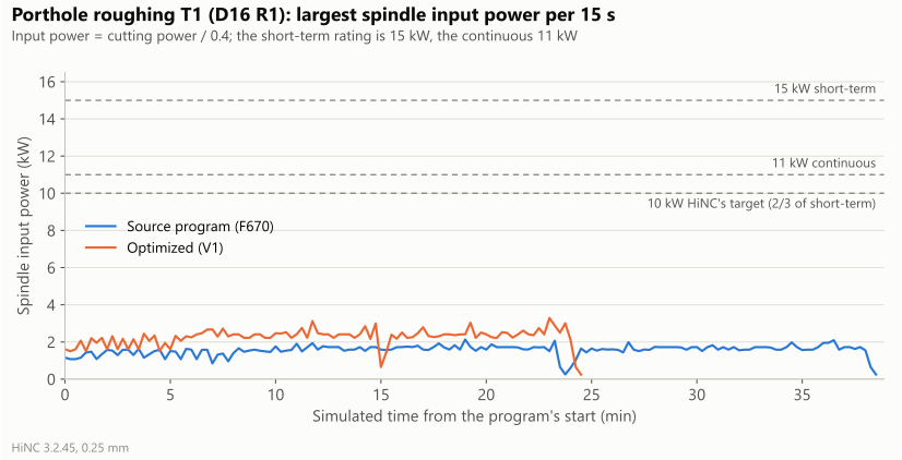
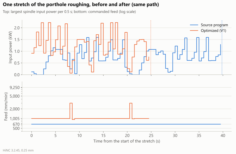
On HiNC 3.2.45 both plates came down from 608.6 to 529.1 simulated minutes (−13.1 %), and the seven programs other than the fin relief from 188.9 to 158.2 (−16.3 %). The roughing took about a third less time, nearly every cutting step at the feed-per-tooth ceiling the agent gave it, 1.5 times the programmed chip, while the spindle stayed under a quarter of its short-term rating. The finishing passes kept their programmed chip, and a force target derived from each tool's compliance trimmed their largest tip deflection, 122 to 78 µm on the wall finishing, for 0.8 % more time. The fin relief's feed through air fell from 125.7 to 77.0 minutes. On the D3 itself, HiNC's default targets took a third off its time and bent it further; a force target set for the 30 µm the case allows drove the feed down to its 30 mm/min minimum and still left 72–82 µm, at an estimated 47 hours for the whole fin relief. Those are the numbers behind sending that relief to EDM.
The study also found where the optimizer's feed for stretches with no contact, the air feed, lands on steel: on a 0.2 mm web at the porthole break-through and on chamfer layers thinner than the 0.25 mm grid, both of which the stock model cannot see. The agent's own exact z-map check found these moves before any program was accepted, and finds none in the final programs. Everything here is simulated: no die was cut, and the times are HiNC's ideal-feed estimates. Each dilemma below gives the risk, how it came to light, the resolution and the evidence that it held.
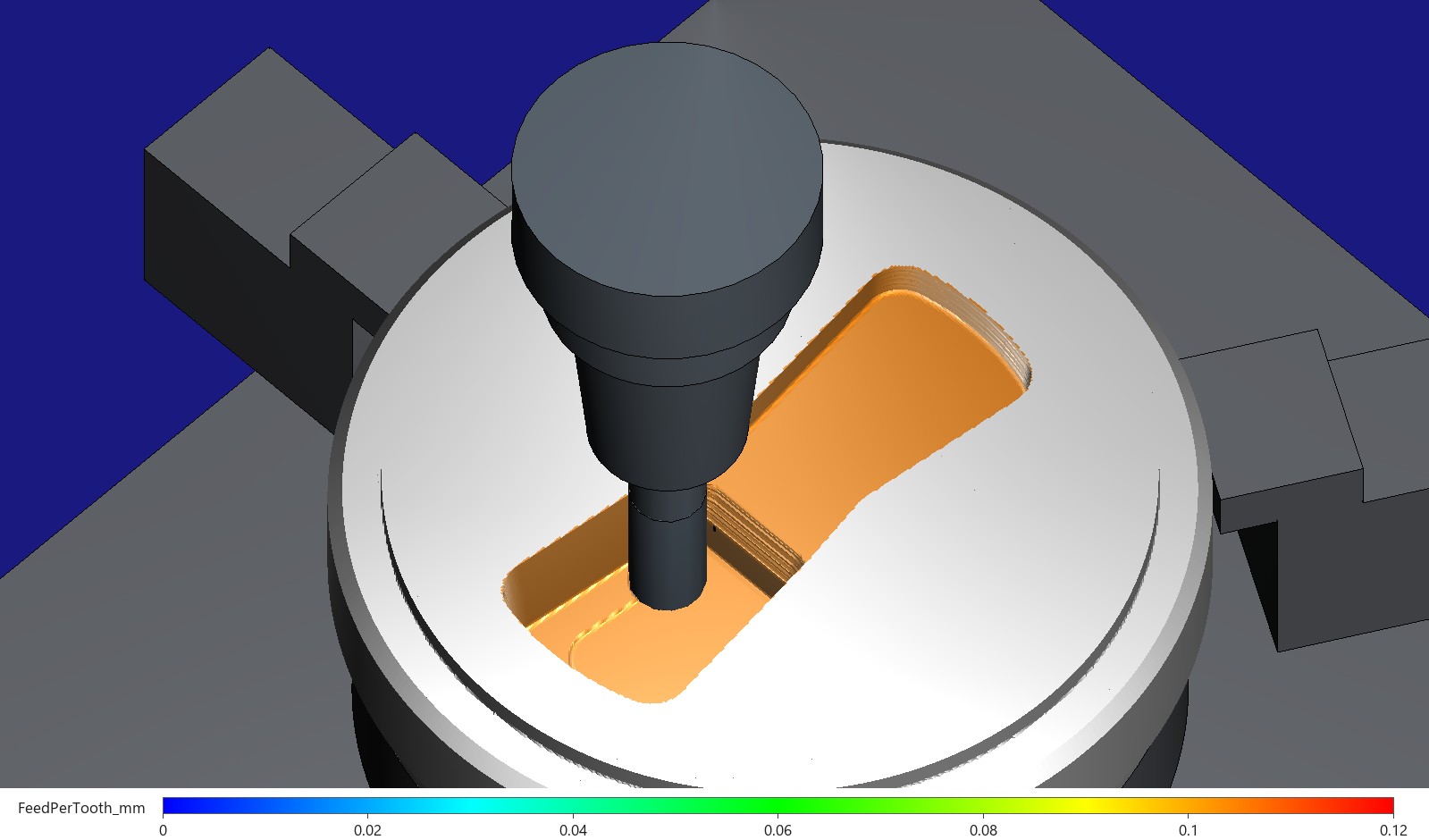
The porthole roughing after HiNC's optimization, paused in the layer at Z −24.8 with the Ø16 end mill in its shrink-fit chuck. The workpiece is coloured by each step's feed per tooth, from 0 to 0.12 mm: every face cut in this play is orange, at the 0.1047 mm ceiling. The same faces before the optimization are green, at the programmed 0.0698 mm (further down). Captured on HiNC 3.2.45.
| Measure | Source programs | Optimized | Change |
|---|---|---|---|
| Simulated machining time, both plates (eight programs) | 608.6 min | 529.1 min | −13.1 % |
| The seven programs other than the D3 fin relief | 188.9 min | 158.2 min | −16.3 % |
| Porthole roughing T1, Ø16 | 38.7 min | 24.6 min | −36.5 % |
| T1's highest spindle power, against the short-term rating (HiNC's target 0.667) | 0.142 | 0.219 | nearly every cutting step at the feed ceiling instead |
| T1's highest tool stress, against yield | 0.141 | 0.206 | |
| The D3 fin relief: feed through air, cutting | 125.7, 291.6 min | 77.0, 291.6 min | air −39 %, cutting held |
| Wall finishing T2: tip deflection p99, largest | 42.3, 122 µm | 38.0, 78 µm | time +0.8 % |
| Milled faces within ±0.15 mm of the model: the portholes' set-up, the pocket, the relief side | 100, 100, 96.087 % | 100, 100, 96.091 % | no point moved more than 0.16 mm |
| The D3 with a force target for C1, 0.1 mm step-down: deflection p99 | 105–129 µm at 300 mm/min | 72–82 µm at 30 mm/min | 30 µm not reached; about 47 h for the whole relief |
| Cutting moves at the air feed, final programs (the agent's z-map) | — | 0 | |
| Run cost of the study, on a shared 32-thread server | 22 plays, 3.5 h | up to 20 GB for an optimization play, 3–5 GB for a replay |
The case
The die and its programs are those of the base case, as accepted there: the agent's model of the paper's proposed die, a generic three-axis machine with a BT40 spindle of 11 kW continuous and 15 kW short-term rating, FDAC pre-hardened die steel with HiNC's shipped cutting parameters, generic carbide tools in shrink-fit holders, and eight Fanuc programs, each with one programmed feed (read):
| Set-up | Program | Tool | Speed (min⁻¹) | Feed (mm/min) | Feed per tooth (mm) | HiNC time (min) |
|---|---|---|---|---|---|---|
| upper plate, joint face up | U1-T1 porthole roughing | T1 Ø16 R1, four flutes | 2,400 | 670 | 0.0698 | 38.73 |
| U1-T2 wall finishing | T2 Ø8, neck Ø7.6 × 58, four flutes | 4,800 | 760 | 0.0396 | 63.29 | |
| upper plate, billet face up | U2-T3 bridge chamfers | T3 Ø6, four flutes | 5,800 | 700 | 0.0302 | 10.20 |
| lower plate, entry face up | L1-T4 pocket roughing | T4 Ø10, four flutes | 3,500 | 700 | 0.0500 | 3.85 |
| L1-T5 pocket finishing | T5 Ø4, neck Ø3.8 × 14, three flutes | 7,200 | 430 | 0.0199 | 10.15 | |
| lower plate, exit face up | L2-T4 run-out step 2 | T4 | 3,500 | 700 | 0.0500 | 15.93 |
| L2-T6 wide relief | T6 Ø6, long neck Ø5.7 × 36, four flutes | 4,800 | 380 | 0.0198 | 46.74 | |
| L2-T7 fin relief | T7 Ø3 (the D3), neck Ø2.8 × 40, two flutes | 8,000 | 300 | 0.01875 | 419.72 | |
| Both plates | 608.6 |
What the base case says about these programs (read): every program played clean at 0.25 mm; the porthole roughing, the heaviest cut, stayed under a fifth of the continuous rating; the D3 takes 419.7 of the 608.6 minutes, and its loads cannot be read at 0.25 mm, where the grid is coarser than its 0.1 mm step-down, only on a block cut down to two fin slots at 0.03125 mm. There the cutter bends several times more than the limit written before the first play, criterion C1: the tip deflection's 99th percentile at most 30 µm and its peak at most 50 µm. By the rule C4 written with it, more than 4 hours for the fin relief at loads that pass C1, the case recommends sinker EDM for that relief.
What HiNC's optimizer does (read, NC Optimization and Workflow: NC Optimization): for every step it solves the feed per tooth at which each switched-on load meets its target (spindle power and torque at 1/1.5 of the short-term rating, the tool's stress at a third of yield through the tool's own safety factor of 3, and a cutting force if a target is given), takes the lowest, bounds it by the feed limits, smooths it over 2 mm before and after and by an acceleration limit, and writes it into the program. A stretch with no contact within those 2 mm gets the feed for non-cutting regions, called the air feed on this page. The loads end up at or under their targets; a replay can read a little above them, because its interpolation points differ.
What the case leaves to the agent: the tools are generic, so no maker's data bounds the feed per tooth; HiNC's optimizer has no deflection criterion, and with HiNC's deflection transformation off, as these projects play, a faster finishing pass bends its tool further without the comparison with the design showing it; and the stock model knows nothing thinner than its grid.
The agent wrote down three questions before the first optimization play:
- How much margin did the roughing leave? The porthole roughing ran at 0.142 of the short-term rating; HiNC's target is 0.667.
- How much of the feed through air can the optimizer take back? The D3 alone feeds through air for 125.7 minutes, mostly lifting out of a slot and coming down again at 300 mm/min. The optimizer can only take back what its stock model shows as air.
- What does holding the finishing and the long-neck tools cost? In particular, how long would the D3 take if its feed alone had to meet C1, the number behind the EDM recommendation.
What the agent built
Each value below is marked read (from the base case or HiNC's documentation), measured (in a play of this study), derived or chosen (the agent's decision). Every variant is one optimization play of the source programs, whose own step data is the “before”, and one replay of the optimized programs on the same machine at the same grid, the “after”.
| Variant | What | Grid | Settings |
|---|---|---|---|
| V1 | the whole die, seven programs | 0.25 mm | the roughing (T1, both T4 programs) up to 1.5 times its programmed chip; the finishing (T2, T5) at its programmed chip, with a force target that trims its deflection peaks; the long-neck T6 up to 1.5 times, with a force target from C1's budget; the D3's cutting lines held at their feed, only its moves through air optimized |
| — | the bridge chamfers, T3 | 0.25 mm | not optimized (dilemma 2); its time stays at 10.20 min |
| V2a | the D3 on the two-slot block, the 0.1 mm step-down band | 0.03125 mm | HiNC's default targets, with a ceiling of 1.5 times the programmed chip |
| V2b | the D3 on the two-slot block, all four step-down bands | 0.03125 mm | a force target of 2.4 N, C1's 30 µm over the D3's compliance of 12.5 µm/N |
The settings per tool in V1:
| Tool | Programmed feed / per tooth | Ceiling per tooth (mm) | Air feed (mm/min) | Force target | Compliance p95 (µm/N), read on | Deflection p99 there (µm) |
|---|---|---|---|---|---|---|
| T1 | 670 / 0.0698 | 0.1047 | 9,250 | — | 0.068, P3, 0.5 mm | 21.0 |
| T2 | 760 / 0.0396 | 0.03959 | 1,850 | 67.1 N | 0.745, P3, 0.5 mm | 49.2 |
| T3 | 700 / 0.0302 | not optimized | — | — | — | — |
| T4 | 700 / 0.0500 | 0.075 | 8,500 | — | 0.092, P1, 0.25 mm | 17.0 |
| T5 | 430 / 0.0199 | 0.01991 | 2,570 | 142.1 N | 0.352, P1, 0.25 mm | 27.2 |
| T6 | 380 / 0.0198 | 0.0297 | 1,950 | 31.5 N | 0.953, P4, 0.5 mm | 54.9 |
| T7, the D3 | 300 / 0.01875 | 0.01875 (V2: 0.0281) | 740 | V2b: 2.4 N | 12.502, V2a, 0.03125 mm | 123.1 |
- Ceiling per tooth (chosen, derived): 1.5 times the programmed feed per tooth for the roughing and T6, which keeps T1's largest chip at 0.105 mm with no radial thinning at half-diameter engagement; the programmed feed per tooth itself for the finishing, so no finishing step runs faster than programmed. The factor 1.5 is the agent's choice, not a catalogue value. It is written both into the tool's optimization limit and into each program's optimization settings.
- Force target = allowed deflection ÷ compliance (derived). The allowed deflection is 50 µm for the finishing tools, a third of the ±0.15 mm design tolerance (chosen), and 30 µm for T6 and the D3, the 99th-percentile budget of C1 (read). The compliance is the 95th percentile of tip deflection over force on the cutting steps of a trial play (measured). It belongs to the tool and the height at which it is loaded more than to the grid, so two of the trials read it at 0.5 mm; O5 checked the result at 0.25 mm.
- Air feed (derived): F = h ÷ sin φ × z × n, the feed at which a residue as thick as the tool's own 99th-percentile deflection, left on a finished wall, gives a chip no thicker than the program's (dilemma 1). h is the programmed chip (the feed per tooth times the sine of the engagement angle, the feed per tooth itself at half-diameter engagement or more), φ the residue's engagement angle (cos φ = 1 − 2 × depth ÷ diameter), z the flutes and n the speed; the result is bounded by the programmed feed below and 20,000 mm/min above.
- Each cutter's optimization limit is written in full through the web API: optimization on, the tool's yield safety factor 3, the minimum-chip and relief-angle limits on (HiNC's defaults), the lowest feed per tooth 0 and the ceiling above. A cutter whose limit is left empty is read with HiNC's default limit, which has no ceiling.
The optimization settings in front of each program (chosen unless marked):
| Setting | Value |
|---|---|
| optimize the feed | on; the D3 in V1: off, so only its moves through air change |
| ceiling per tooth | as in the table above (derived) |
| lowest feed | 30 mm/min, a tenth of the lowest programmed feed (HiNC's default is 1) |
| highest feed | 20,000 mm/min, under the machine's 24,000 mm/min rapid |
| air feed | per tool, as above (derived) |
| highest acceleration | 1,000 mm/s² (HiNC's default is 10) |
| source-feedrate floor | on at 0.5: no step slower than half its programmed feed; off in V2b, whose target asks for less |
| spindle power and torque safety factors | 1.5, so 0.667 of the short-term rating (read, HiNC's default) |
| yield safety factor in the settings | 0, so the tool's own factor of 3 applies: stress at most 0.333 of yield (read, HiNC's default) |
| force target | as in the table above; none elsewhere (derived) |
| extended distance before and after | 2 mm each (read, HiNC's default) |
| forward, side and depth compensation; depth splitting | off |
The trials, played before the whole die (coarse or cut down):
| Trial | What was played | What it was for |
|---|---|---|
| P0 | the two-slot block at 0.25 mm, only the D3's moves through air optimized, and its replay | whether the acceptance grid sees the D3's 0.1 mm layers well enough that the air feed falls only in air |
| P1 | the pocket set-up at 0.25 mm, T5's force target off, and its replay | whether the optimizer changes this dialect's feeds, whether the replay is clean, T5's compliance |
| P2 | the bridge-chamfer set-up at 0.25 mm, and its replay | T3's compliance, and the air feed on 0.1 mm chamfer layers |
| P3 | the porthole set-up at 0.5 mm, T2's force target off | T2's compliance, and the time and memory of an optimization play |
| P4 | the relief set-up's T4 and T6 at 0.5 mm, T6's force target off | T6's compliance and cost |
Grids. V1 plays at 0.25 mm, the acceptance grid: the roughing layers (0.8 and 1.0 mm), T2's 0.3 mm wall stock and T6's 0.3 mm layers are thicker than a cell, while T3's 0.1 mm layers, T5's 0.2 mm floor and the D3's 0.1 mm are not, so their air feed is what the guard below watches. V2 plays at 0.03125 mm, finer than the thinnest step-down (0.035 mm). 0.5 mm serves only for compliance and cost.
The held break-through. T1 is optimized from a copy of its program in which the lines that end
below z −44.85, the last layer through the plate (196 lines in two blocks), are wrapped in HiNC's
@@BeginPreserve() … @@^EndPreserve() commands, and the programmed F670. is restated on the first
line of each block; motion and feed are otherwise unchanged (dilemmas 4 and 5).
How the agent managed the work
- A plan and its criteria before the first optimization play. The variants, every setting with its source, the guards and eight criteria were written down and committed before the first optimization play. What changed after the trials (the air-feed rule, T3 held, the z-map's tolerance and its stock bottom, the held break-through, reading by path length) is recorded beside the plan as changes; no criterion was rewritten, and those not met are reported as not met.
- Trials before the whole die. Five trials, coarse or cut down, came before V1 (table above).
- Its own check after HiNC's. After every optimization the agent replayed the optimized programs on its own exact z-map of the stock (the project's stock model with its top and bottom faces, a 0.1 mm grid, the programs in the order played) and looked for any move that removes stock at a feed above its tool's ceiling, which is the air feed landing on steel. The same tool split every program into cutting, feed through air and rapid.
- Watching the long plays. Every play longer than about ten minutes was looked at every three minutes with read-only requests: alarms, the current tool and line, the share of recent steps in contact and their loads.
- A shared server. The plays ran on a private HiNC instance on a 32-thread server that other optimization studies and live service instances used at the same time. Heavy plays waited for a shared lock that lets one run at a time, and started only with 40 GB of memory free.
- Where a person stepped in. HiNC's product owner asked for NC-optimization showcases built on accepted cases; the variants, the settings and the criteria are the agent's. No second agent re-ran the study.
The criteria as they were committed before the first optimization play:
| # | Criterion |
|---|---|
| O1 | every optimized program replays to its last line with no alarm the source play did not have: no collision, no rapid through stock, no stroke limit, no new warning or error |
| O2 | the governing loads within their targets on at least 99 % of the cutting steps: spindle power and torque at most 0.667 of the short-term rating, tool stress at most 0.333 of yield, and, where a force target is set, the force at or under it (a replay may read a little above, as HiNC's documentation says) |
| O3 | the shape unchanged: per set-up, the share of milled-face points within ±0.15 mm of the design changes by at most 0.1 percentage point, and no point moves more than 0.25 mm (one cell) |
| O4 | the expected time: roughing at most 0.80 of the source; finishing within −20 % and +5 %; T6 no slower; the D3 in V1 saving at least half of its feed through air, with every cutting move still at 300 mm/min |
| O5 | finishing deflection not larger: T2, T3 and T5 at p50, p99 and largest at most the source's × 1.02 + 1 µm; T6's p99 at most max(30 µm, the source's p99) × 1.05 |
| O6 | the air-feed guard: no move that removes stock above its tool's ceiling in any optimized program, and each tool's contact path within ±3 % of the source's |
| O7 | the output is a real optimization: every optimized file differs from its source, and the optimization reports both of its completion messages with no failed step |
| O8 | C1 for the D3 with the force target (V2b): in every step-down band, the deflection's p99 at most 30 µm and its largest at most 50 µm |
The dilemmas
1. The air feed meets what a finishing pass leaves
Situation. The first pocket trial gave every stretch with no contact one air feed, 20,000 mm/min. Many of those stretches run along a contour that the finishing pass has just cut. Risk. A finishing tool is pushed away from the wall by as much as it bends and leaves that much stock behind; a free-running tool at 46 times its programmed feed per tooth then cuts it. Noticed in HiNC's own replay of the trial: eight T5 steps read a stress ratio of 1.25–1.56 and 320–397 N, all at F20,000 along finished walls, with a modelled contact under 0.004 mm wide and 0.93 mm per tooth. Resolution. Each tool's air feed is set so that a residue as thick as its own 99th-percentile deflection gives no thicker chip than the program's: 740 to 9,250 mm/min instead of 20,000. Evidence. In V1's pocket replay T5's highest stress ratio is 0.332.
2. A layer thinner than the grid
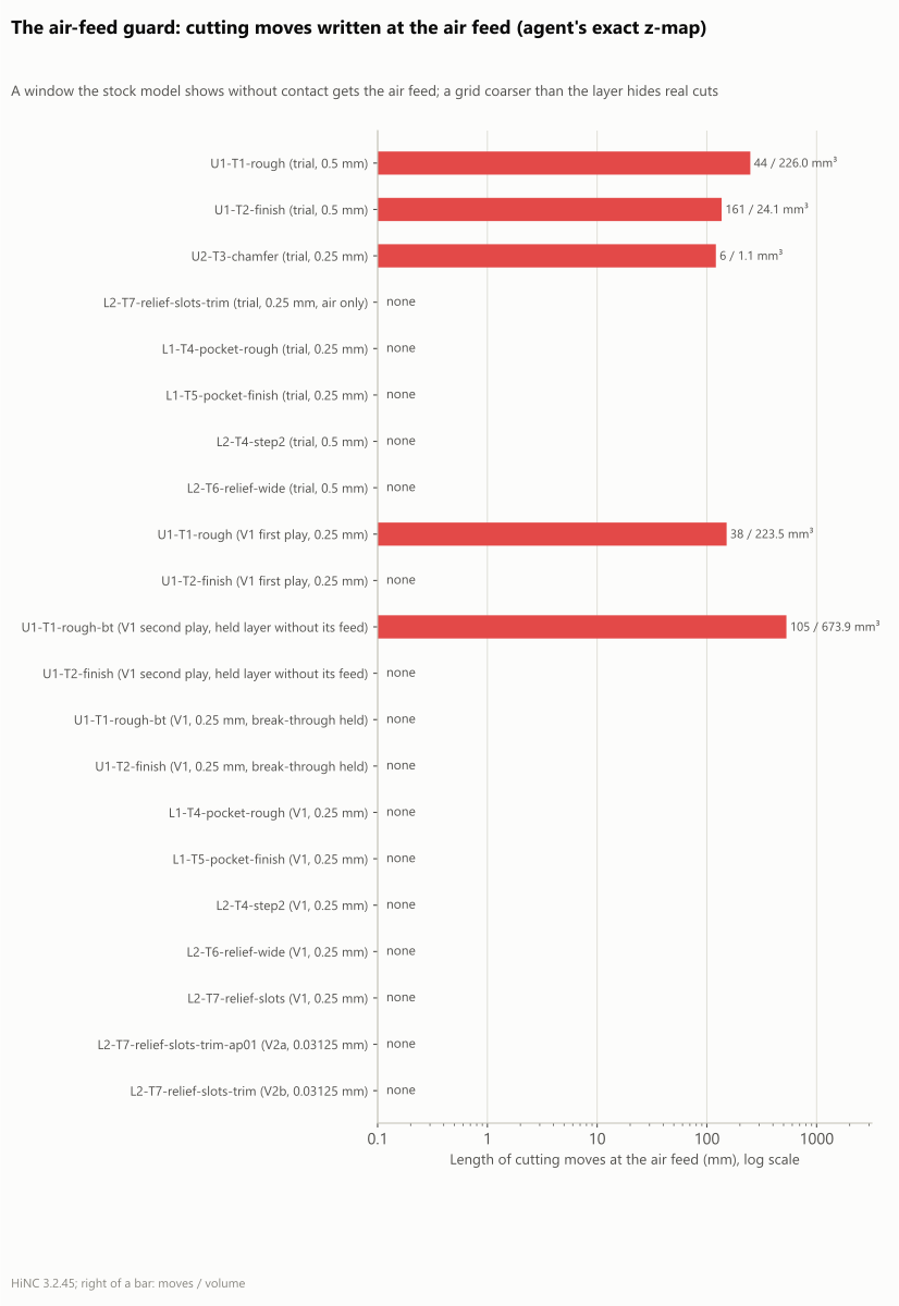
Situation. The bridge chamfers are cut in 0.1 mm layers; the acceptance grid is 0.25 mm. Risk. The stock model does not see the layer, and the optimizer writes a cutting pass at the air feed. Noticed by the agent's z-map: in the chamfer trial six moves at F20,000 still cut the chamfer's thin layers, 1.1 mm³ over 120.8 mm. Resolution. T3 is not optimized: in the trial the optimization took only 38 seconds off its 10.2 minutes, not worth a finer grid for the whole plate. Evidence. T3's program stays as accepted, 10.20 minutes.
3. A 0.5 mm grid coarser than the wall stock
Situation. To save run time, the compliance trials of the porthole and relief set-ups played at 0.5 mm. Risk. Using an optimized program from that grid. Noticed by the z-map: in the porthole trial 44 T1 moves and 161 T2 moves cut at the air feed, through T2's 0.3 mm wall stock and the 0.2 mm web the last T1 layer leaves. Resolution. 0.5 mm serves only for compliance and cost; V1 plays at 0.25 mm. Evidence. V1 met O5 at 0.25 mm with force targets derived from the 0.5 mm compliances.
4. A 0.2 mm web at the break-through
Situation. T1 roughs the portholes through the 45 mm plate; on its last layer the plate's bottom is a web 0.2 mm thick, thinner than a cell. Risk. The first V1 program ran 38 moves of that layer at the air feed, F9,250, almost fourteen times the programmed feed. Noticed only by the agent's z-map: HiNC's replay at the same grid had no step above the ceiling in contact, because the web is not in its stock model. Resolution. The break-through layer, the lines that end below z −44.85, is held at its programmed feed with HiNC's preserve commands. Evidence. 0 such moves in the final program.
5. A held block runs at the feed of the line before it
Situation. With the break-through layer held, the guard still found 105 moves of that layer at
F9,250. The source program writes F670. only twice, once as each porthole begins, so the held lines
carry no feed word of their own; HiNC copies held lines into the optimized file word for word, and they run at the modal
feed the optimizer wrote on the line before the block, here the air feed. Risk. The layer “held at
its programmed feed” becomes the fastest cut of the program. Noticed by the z-map; HiNC's replay
of that program read 4,029 N, a stress ratio of 0.81 and a power ratio of 0.51 at the break-through.
Resolution. The agent restated the programmed feed on the first line of each held block. The
optimized file then reads, around the first block:
X-35.177 Y-7.377 F9250 (src(LineNo: 3675, StepIndex: 58362))
X-25.3 Y-6.186 Z-44.647 (src(LineNo: 3676, StepIndex: 58398))
Y0.986 Z-44.898 F670. (@@BeginPreserve();)
X-41.073 Y2.888 Z-45.453
X-41.133 Y1.842 Z-45.489
Evidence. The final program has no cutting move at the air feed; its replay's highest T1 force is 1,152 N and its highest stress ratio 0.206.
6. The agent's own check raised two false alarms
Situation. Twice the z-map reported a danger that was not there: on a T5 contour run three times, whose second and third passes are in air, cells right on the cutter's radius were “cut again” when the sample point moved; and, before it had the stock's bottom face, it counted T2's finishing pass through the bottom of the plate as cutting steel below the plate (396 moves). Risk. Changing a program for an artefact, or ceasing to trust the check. Noticed by going back to the source lines: the same contour three times, and z −46 under a 45 mm plate. Resolution. The z-map counts stock only 0.005 mm inside the cutter's radius and 0.002 mm above its tip, and holds both faces of the stock; every check was rerun. Evidence. Both cases read 0 afterwards.
7. Per-step statistics skewed by the slow-downs
Situation. HiNC writes one step per spindle revolution, so a stretch the optimizer slows down gets more steps per millimetre. Risk. T2's median deflection seemed to grow from 14.1 to 15.7 µm while no place on the path bent further. Noticed comparing feeds step by step: the slowed corners carried several steps per mm. Resolution. O2 and O5 weight each step by its path length; read that way, T2's median goes from 13.7 to 13.6 µm. Evidence. Both readings are kept; the largest values are the same either way, and every load on this page is weighted by path length.
8. A replay that straddles the force target
Situation. On T6 the optimizer set 34.8 % of the cutting steps to exactly the force target, 31.5 N; the replay, with other interpolation points, put 13.1 % of the cutting path above it (the source program: 9.6 %). Risk. Calling “a little above the target” a failure, or hiding a real excess. Noticed by O2. Resolution. Judged as written: O2 is not met for T6. Reported beside it: the path above 1.05 times the target fell from 3.5 % to 1.9 %, above 1.2 times from 0.79 % to 0.30 %, and the largest from 3.76 to 3.17 times. Evidence. The criteria's record.
9. The D3's loads at 0.25 mm are not real
Situation. At the acceptance grid the D3's 0.1 mm layer is thinner than a cell: HiNC reads a stress ratio of 1.216 and a deflection of 1,357 µm, against 0.13 and 143 µm on the two-slot block at 0.03125 mm. Risk. The optimizer slowing the D3 for loads that are not there, or speeding it where a real cut looks like air. Resolution. In V1 the D3's cutting lines keep their feed and only its moves through air are optimized; its loads are read on the two-slot block in V2. Trial P0 first showed, on the block at 0.25 mm, that the air feed then falls only in air. Evidence. In V1 every D3 cutting move is still at 300 mm/min, and the guard found no move.
10. C1 cannot be reached by feed
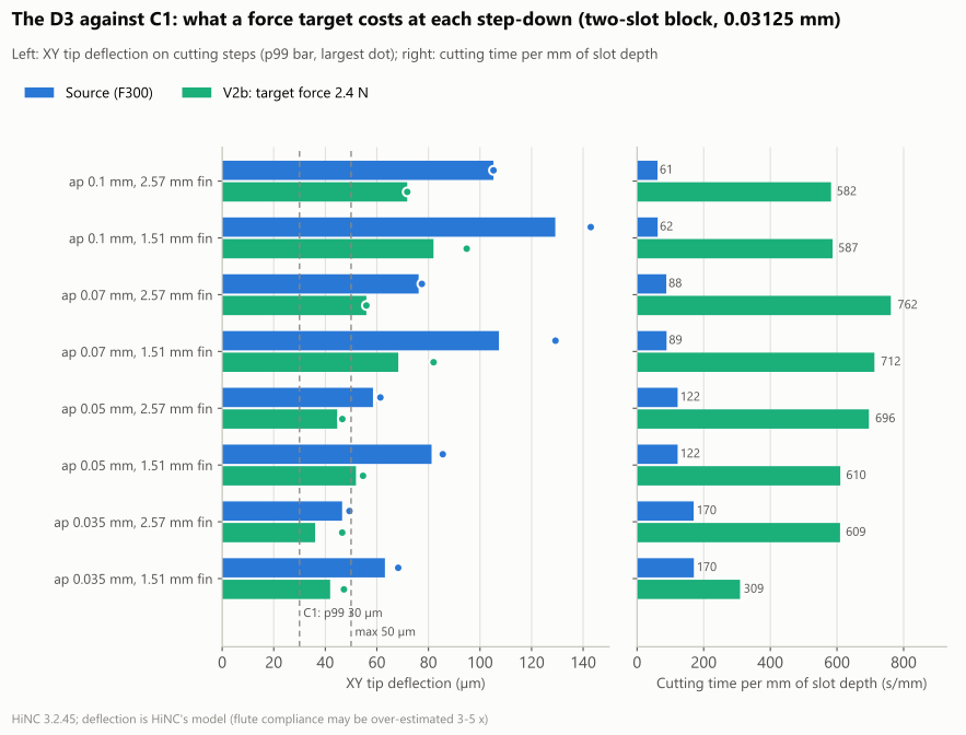
Situation. With the force target set for C1, 2.4 N, the optimizer drove the feed to its 30 mm/min minimum in every band, and the replay still bent 72–82 µm (p99) at a 0.1 mm step-down and 36–42 µm at 0.035 mm. A tenth of the feed only halved the force, from 6.9 to 3.4 N at 0.1 mm: HiNC's force keeps a part that does not fall with the feed per tooth, the edge's ploughing and rubbing. Risk. Writing “slow down to so many mm/min and C1 holds”. Noticed reading the replay band by band. Resolution. O8 is reported as not met, with the model's two leanings: HiNC reads the depth in these narrow slots as twice the programmed step-down, and the flute compliance may be over-estimated; both raise the floor of the force and of the bending. Neither changes the direction. Evidence. The band table and the whole-program hours below.
11. Two locks waiting for each other
Situation. HiNC's canvas is captured from a desktop that drives the server's instance, one capture at a time under the desktop's lock. The picture play took the server's shared lock, paused at its line, and then waited for the desktop's lock, which another case's capture had held for over an hour. Risk. Every Showcase play on the server queued behind a paused picture play; had the other case been waiting for the server's lock, neither would ever have moved. Noticed when the server's lock had been held by a paused play for over 25 minutes. Resolution. The agent stopped its picture play and reordered: the desktop's lock first, then the picture play, which no longer queues for the server's lock. It plays only T1 up to one line and writes no step data, about 1.5 GB for three minutes, lighter than the trials. Evidence. The two picture plays took 160 s at 1.55 GB and 112 s at 1.40 GB.
12. Before and after pictures from two cameras
Situation. In the first pair of pictures the fixture sat about 60 pixels higher in one than in the other. Risk. Reading a camera difference as the optimization's. Noticed side by side. Cause. HiNC's isometric view fits the tool-path points that lie in the path strip's display range; during a play that range follows the last stretch, the two programs have different numbers of steps per mm, and the first pair had also paused on a ramp between layers. Resolution. Before each capture the display range is set to the whole path played so far, and the play pauses in the middle of a layer. Evidence. The fixture and background of the two pictures differ by 0 pixels.
Results and benefits
Measured on HiNC 3.2.45 at 0.25 mm unless stated. Each optimization play also played the source programs, so before and after come from the same build, machine and grid; HiNC's time for the source programs is the base case's 608.6 minutes, program by program. The times are ideal-feed estimates with no tool change, turn-over or wire EDM (Machining Time Estimation): the ratio carries over to a machine, the minutes do not.
Both plates, program by program
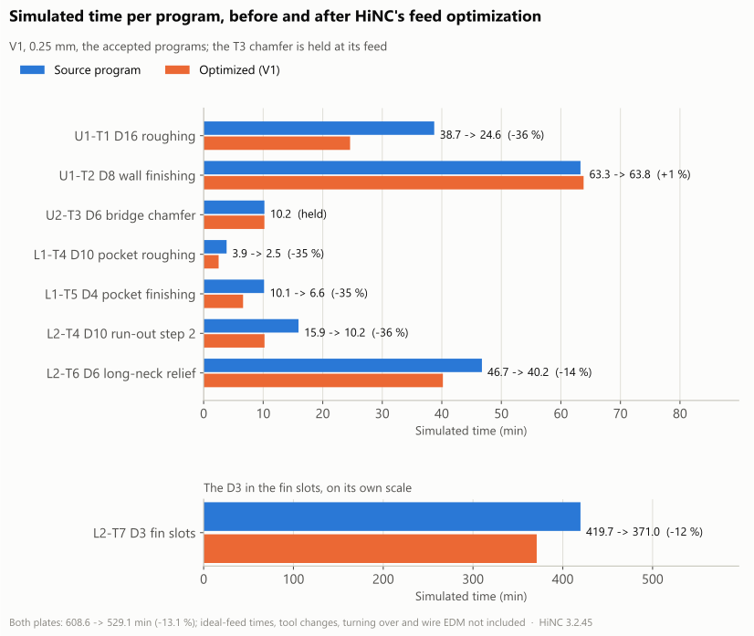
| Program | Class | Source (min) | Optimized (min) | Change | Cutting / air / rapid, source (min) | Cutting / air / rapid, optimized (min) |
|---|---|---|---|---|---|---|
| U1-T1 porthole roughing, Ø16 | roughing | 38.73 | 24.60 | −36.5 % | 36.0 / 2.7 / 0.0 | 23.7 / 0.8 / 0.0 |
| U1-T2 wall finishing, Ø8 | finishing | 63.29 | 63.81 | +0.8 % | 60.6 / 2.7 / 0.0 | 61.0 / 2.8 / 0.0 |
| L1-T4 pocket roughing, Ø10 | roughing | 3.85 | 2.52 | −34.7 % | 3.7 / 0.1 / 0.0 | 2.4 / 0.0 / 0.0 |
| L1-T5 pocket finishing, Ø4 | finishing | 10.15 | 6.62 | −34.7 % | 5.6 / 4.5 / 0.0 | 5.6 / 0.9 / 0.0 |
| L2-T4 run-out step 2, Ø10 | roughing | 15.93 | 10.22 | −35.8 % | 15.2 / 0.7 / 0.0 | 10.0 / 0.2 / 0.0 |
| L2-T6 wide relief, Ø6 long neck | long-neck semi-finishing | 46.74 | 40.18 | −14.0 % | 39.1 / 7.5 / 0.1 | 35.2 / 4.8 / 0.1 |
| L2-T7 fin relief, the D3 | Ø3 long neck | 419.72 | 370.96 | −11.6 % | 291.6 / 125.7 / 2.4 | 291.6 / 77.0 / 2.4 |
| U2-T3 bridge chamfers, Ø6 | finishing | 10.20 | 10.20 | held | 7.7 / 2.1 / 0.4 | 7.7 / 2.1 / 0.4 |
| Both plates | 608.6 | 529.1 | −13.1 % |
The split into cutting, feed through air and rapid is the agent's z-map: a move cuts when it removes more than 0.01 mm³ of the stock, and a time is its length over its feed.
Where the time goes
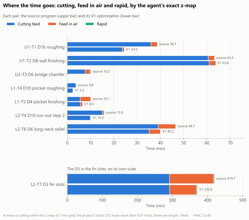
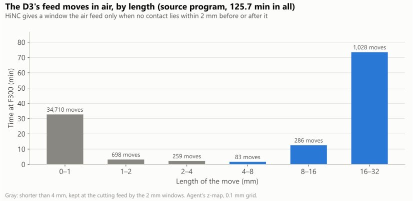
- HiNC changes a stretch to the air feed only when no contact lies within 2 mm before or after it. Of the D3's 125.7 minutes through air, 34,710 moves are shorter than 1 mm (32.7 minutes): the lifts and plunges inside a slot, which stay at the cutting feed. What can be saved lies in 1,028 exits of 16–32 mm (73.5 minutes) and 286 moves of 8–16 mm (12.5 minutes). With the D3's air feed held to the residue rule's 740 mm/min, 48.8 minutes came back.
- The pocket finishing, T5, is a finishing pass that came out 35 % faster: 4.5 of its 10.1 minutes were feed through air, among them the same outer contour at z −5 run three times, twice in air. Its cutting time did not change.
- The wall finishing, T2, gained nothing in air: its moves through air are mostly short or within 2 mm of contact, and its air feed is held to 1,850 mm/min. The 0.9 % of its steps slowed by the force target added 0.4 minutes.
The porthole roughing: at the feed ceiling, far from the spindle
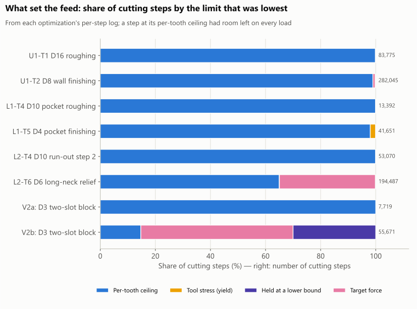
| Program | Cutting steps | Feed-per-tooth ceiling | Target force | Tool stress | Power / torque | Held at a lower bound |
|---|---|---|---|---|---|---|
| U1-T1 porthole roughing, Ø16 | 83,775 | 99.9 % | 0.0 % | 0.1 % | 0.0 % | 0.0 % |
| U1-T2 wall finishing, Ø8 | 282,045 | 99.0 % | 0.9 % | 0.0 % | 0.0 % | 0.2 % |
| L1-T4 pocket roughing, Ø10 | 13,392 | 99.9 % | 0.0 % | 0.0 % | 0.0 % | 0.0 % |
| L1-T5 pocket finishing, Ø4 | 41,651 | 98.0 % | 0.0 % | 1.9 % | 0.0 % | 0.0 % |
| L2-T4 run-out step 2, Ø10 | 53,070 | 100.0 % | 0.0 % | 0.0 % | 0.0 % | 0.0 % |
| L2-T6 wide relief, Ø6 long neck | 194,487 | 65.0 % | 34.8 % | 0.1 % | 0.0 % | 0.1 % |
| V2a: the D3 on the two-slot block | 7,719 | 100.0 % | 0.0 % | 0.0 % | 0.0 % | 0.0 % |
| V2b: the D3 on the two-slot block | 55,671 | 14.7 % | 55.3 % | 0.0 % | 0.0 % | 30.0 % |
- The table and the chart come from the optimizer's per-step log, which gives for every step the feed
each criterion allows; the lowest is the step's. These plays kept the smoothing on (the 2 mm windows
and the acceleration limit), which, as HiNC's documentation says, carries neighbouring steps into what
the log records, so the shares are the limits as the log records them, not each step tested on its own
with the smoothing off. A criterion whose load stays under its target
over the whole feed range ends its search at the range's top and is marked
[OverIteration]in that log: read it as “did not limit this step”. - Of T1's 83,775 cutting steps, 99.87 % ran at the ceiling, 0.1 % were held by the tool's stress and 0.03 % by the lower bound; power and torque limited none. The optimized program's highest short-term power ratio is 0.219 (0.299 of the continuous rating), far from HiNC's 0.667. How much faster this program can go is set by the ceiling, not by the spindle, and the ceiling is the agent's 1.5 times the programmed chip: another ceiling gives another result.
- Both T4 programs also ran at the ceiling: 3.85 to 2.52 and 15.93 to 10.22 minutes, force p99 203 to 282 N, stress ratio up to 0.25.
- “Held at a lower bound” is half the programmed feed in V1 and the 30 mm/min minimum in V2b, which ran with that floor off. In V1 most of those steps are plunges on which HiNC reads no load at all: the optimizer solves a step with zero load to the lower bound rather than the ceiling. It concerns 371 of T2's steps and 23 of T1's.
HiNC's canvas: one roughing layer before and after
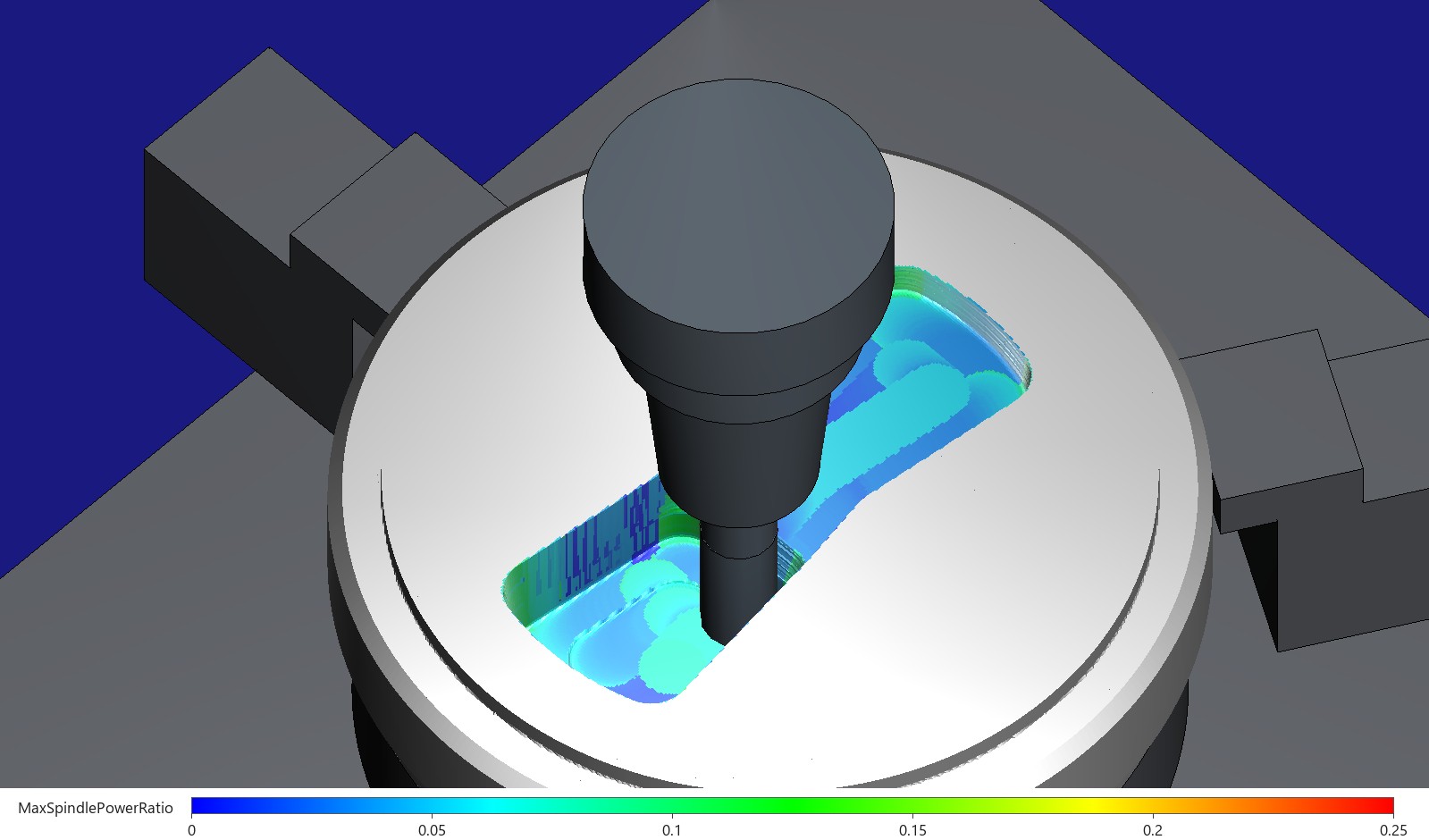
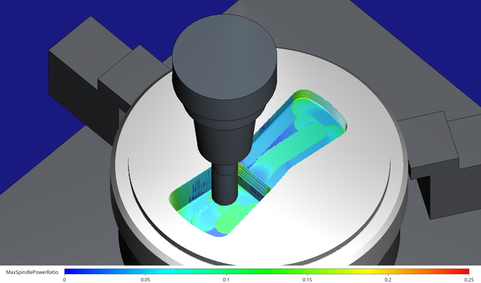
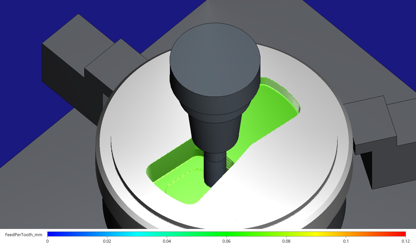
The porthole roughing, T1, paused in the same layer, Z −24.8, source lines 2216–2259: the source program at line 2233, the optimized one at its line for source line 2234, the Ø16 end mill in its shrink-fit chuck in view. Above: coloured by short-term spindle power ratio, 0 to 0.25; below: by feed per tooth, 0 to 0.12 mm, whose optimized picture opens this page. HiNC's linear colour scale runs blue at the bottom, green in the middle and red at the top and above; a face takes the colour of the last step that cut it, and the bar under each picture is drawn from HiNC's rule without the canvas's lighting. Captured on HiNC 3.2.45.
The three layers in these pictures (Z −23.2 to −24.8, source lines 2097–2233), cutting steps weighted by path length:
| Source | Optimized | |
|---|---|---|
| Cutting steps | 1,852 | 1,277 |
| Path | 504.9 mm | 499.5 mm |
| Short-term power ratio p50 / p95 / largest | 0.042 / 0.072 / 0.115 | 0.059 / 0.100 / 0.161 |
| Feed per tooth p50 | 0.0698 mm | 0.1047 mm |
HiNC's power target, 0.667, lies far beyond the top of the colour scale; the optimized layer's cutting steps run at the ceiling, which is what “at the feed ceiling, not at the spindle” looks like.
Finishing and the long-neck tools
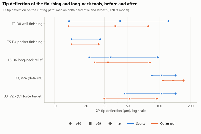
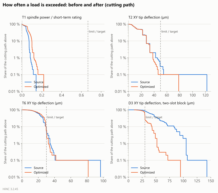
| Program | Power, short-term, largest | Power, continuous, largest | Tool stress, largest | Force p99 / largest (N) | XY tip deflection p50 / p99 / largest (µm) |
|---|---|---|---|---|---|
| U1-T1 porthole roughing, Ø16 | 0.142 → 0.219 | 0.194 → 0.299 | 0.141 → 0.206 | 295 / 748 → 426 / 1,152 | 12.6 / 18.8 / 41.8 → 17.8 / 26.8 / 57.6 |
| U1-T2 wall finishing, Ø8 | 0.020 → 0.012 | 0.027 → 0.017 | 0.151 → 0.095 | 61 / 179 → 55 / 111 | 13.7 / 42.3 / 122.3 → 13.6 / 38.0 / 78.3 |
| L1-T4 pocket roughing, Ø10 | 0.053 → 0.073 | 0.072 → 0.099 | 0.180 → 0.249 | 203 / 322 → 282 / 451 | 15.3 / 17.0 / 27.4 → 21.2 / 22.9 / 37.5 |
| L1-T5 pocket finishing, Ø4 | 0.013 → 0.013 | 0.018 → 0.017 | 0.344 → 0.332 | 83 / 83 → 80 / 80 | 14.5 / 27.2 / 27.2 → 14.5 / 26.2 / 26.3 |
| L2-T4 run-out step 2, Ø10 | 0.046 → 0.063 | 0.063 → 0.086 | 0.113 → 0.154 | 203 / 203 → 282 / 282 | 4.7 / 16.9 / 17.4 → 5.3 / 22.9 / 23.6 |
| L2-T6 wide relief, Ø6 long neck | 0.017 → 0.013 | 0.023 → 0.018 | 0.137 → 0.116 | 37 / 118 → 36 / 100 | 21.4 / 34.3 / 96.6 → 24.0 / 32.4 / 81.5 |
| L2-T7 fin relief, the D3 (0.25 mm: not real loads) | 0.009 → 0.009 | 0.013 → 0.013 | 1.216 → 1.216 | 19 / 120 → 19 / 120 | 105.1 / 232.8 / 1,356.9 → 105.1 / 232.8 / 1,356.9 |
- T2, the wall finishing (Ø8 with a Ø7.6 × 58 neck): its chip held at the programmed value and its force target at 67.1 N. The optimizer slowed only 0.85 % of the cutting steps, where the force was over 67 N. Per mm of path the deflection's p50 went from 13.7 to 13.6 µm, its p99 from 42.3 to 38.0 and its largest from 122 to 78 µm; the path over the target fell from 0.8 % to 0.05 %.
- T5, the pocket finishing (Ø4): its force target of 142 N never applied. 1.8 % of its path had run above a stress ratio of 0.333 (at most 0.344); the optimizer slowed those 1.9 % of steps, and the replay's highest is 0.332.
- T6, the long-neck relief (Ø6 with a Ø5.7 × 36 neck, 45 mm out): ceiling 1.5 times, force target 31.5 N. 34.8 % of its cutting steps were set by the force and 65 % ran at the ceiling: faster where it is light, slower where it is heavy. The deflection's p50 went from 21.4 to 24.0 µm, its p99 from 34.3 to 32.4 and its largest from 96.6 to 81.5 µm, in 40.18 minutes instead of 46.74.
- The deflection is HiNC's model, in which the flute's compliance may be over-estimated three to five times; the comparisons hold within the model.
The D3 in the fin slots: what feed alone can do
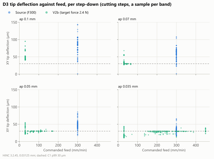
- V2a, HiNC's default targets with the 1.5-times ceiling, on the 0.1 mm band: all 7,719 cutting steps ran at the ceiling (stress ratio 0.13 to 0.15; power and torque negligible), and the band's time fell from 6.65 to 4.45 minutes (−33 %). Per mm of path the deflection's p50 went from 85 to 109 µm, its p99 from 105 to 135 µm and its largest from 143 to 170 µm (step by step the p99 reads 123 to 147 µm). HiNC's optimizer has no deflection criterion: given only its default targets, it bends a long-neck tool further.
- V2b, a force target of 2.4 N on all four bands: of 55,671 cutting steps, 55 % were set by the force, 30 % held at the 30 mm/min minimum (the target wanted less) and 15 % ran at the ceiling (the force stays under 2.4 N even there). The replay's median feed is 30 mm/min in every band, yet the force only went from 6.9 to 3.4 N at 0.1 mm: ten times slower, half the force. The deflection's p99 stays at 72–82 µm at 0.1 mm, 56–68 at 0.07, 45–52 at 0.05 and 36–42 µm at 0.035 mm; none of the four bands meets C1, and only the 0.035 mm band keeps its largest under 50 µm.
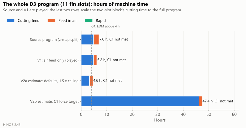
- The two-slot block's simulated time went from 47.8 to 286.7 minutes, six times as long. Scaled by the 0.1 mm band's ratio (9.49 times) to the whole program's 291.6 minutes of cutting, the whole D3 would take 47.4 hours and still not meet C1. That ratio is of the cutting time; the band's whole time grew 9.98 times, because at 30 mm/min some contact removes too little to count as cutting and the short moves inside the slots slow down too. Scaled by that ratio instead, the whole D3 comes to about 50 hours.
- Read it knowing two things: HiNC reads the depth in these narrow slots as twice the programmed step-down, and the force's ploughing part grows with depth, so the model's floor of the force may be high; the compliance may be over-estimated too. The direction stands all the same: feed alone does not meet C1. What remains is a shorter-necked tool in stages or EDM, the reason the base case recommended EDM, now with numbers.
The two-slot block band by band (V2a and V2b are the optimization plays, which played the source program; V2ar and V2br are the replays of the optimized programs):
| Play | Step-down (mm) | Fin (mm) | Time (s) | Cutting time (s) | Cutting feed p50 (mm/min) | Deflection p50 / p99 / largest (µm) | Force p50 / p99 (N) | Cutting s per mm of slot depth |
|---|---|---|---|---|---|---|---|---|
| V2a | 0.1 | 2.57 | 197 | 184 | 300 | 85.0 / 105.2 / 105.2 | 6.93 / 8.60 | 61 |
| V2a | 0.1 | 1.51 | 199 | 185 | 300 | 83.3 / 129.2 / 143.0 | 6.80 / 10.40 | 62 |
| V2ar | 0.1 | 2.57 | 131 | 124 | 450 | 108.6 / 135.0 / 135.0 | 8.97 / 11.17 | 41 |
| V2ar | 0.1 | 1.51 | 133 | 124 | 450 | 107.0 / 156.0 / 170.4 | 8.84 / 12.68 | 41 |
| V2b | 0.1 | 2.57 | 198 | 184 | 300 | 85.0 / 105.2 / 105.2 | 6.93 / 8.60 | 61 |
| V2b | 0.1 | 1.51 | 199 | 185 | 300 | 83.3 / 129.2 / 143.0 | 6.80 / 10.40 | 62 |
| V2b | 0.07 | 2.57 | 282 | 263 | 300 | 57.9 / 76.2 / 77.5 | 4.73 / 6.07 | 88 |
| V2b | 0.07 | 1.51 | 284 | 266 | 300 | 57.0 / 107.3 / 129.3 | 4.66 / 8.64 | 89 |
| V2b | 0.05 | 2.57 | 393 | 365 | 300 | 48.3 / 58.5 / 61.4 | 3.94 / 4.78 | 122 |
| V2b | 0.05 | 1.51 | 396 | 365 | 300 | 46.5 / 81.2 / 85.6 | 3.75 / 6.53 | 122 |
| V2b | 0.035 | 2.57 | 554 | 510 | 300 | 33.3 / 46.5 / 49.4 | 2.71 / 3.74 | 170 |
| V2b | 0.035 | 1.51 | 559 | 511 | 300 | 30.7 / 63.1 / 68.3 | 2.50 / 5.07 | 170 |
| V2br | 0.1 | 2.57 | 1,973 | 1,747 | 30 | 43.2 / 71.8 / 71.8 | 3.44 / 5.74 | 582 |
| V2br | 0.1 | 1.51 | 1,991 | 1,761 | 30 | 41.6 / 82.0 / 94.8 | 3.32 / 6.54 | 587 |
| V2br | 0.07 | 2.57 | 2,560 | 2,285 | 30 | 30.2 / 55.9 / 55.9 | 2.40 / 4.47 | 762 |
| V2br | 0.07 | 1.51 | 2,404 | 2,137 | 30 | 30.1 / 68.3 / 82.0 | 2.40 / 5.45 | 712 |
| V2br | 0.05 | 2.57 | 2,363 | 2,088 | 30 | 30.0 / 44.6 / 46.6 | 2.40 / 3.56 | 696 |
| V2br | 0.05 | 1.51 | 2,054 | 1,830 | 30 | 30.0 / 51.9 / 54.6 | 2.40 / 4.14 | 610 |
| V2br | 0.035 | 2.57 | 2,023 | 1,828 | 30 | 29.4 / 36.0 / 46.6 | 2.40 / 2.97 | 609 |
| V2br | 0.035 | 1.51 | 1,829 | 927 | 30 | 29.6 / 41.9 / 47.2 | 2.40 / 3.35 | 309 |
Cutting time counts the steps in contact that remove more than 0.01 mm³/s. At 30 mm/min some contact falls below that in every band, and most beside the 1.51 mm fin in the 0.035 mm band: there 877 s of contact are not in the 927 s, so its 309 s per mm is not a faster cut. That band took 1,829 s in all, against 2,023 s beside the 2.57 mm fin.
The whole D3 program, eleven fin slots:
| Cutting (h) | Feed through air (h) | Rapid (h) | Total (h) | 0.1 mm band p99 / largest (µm) | C1 | EDM by C4 | |
|---|---|---|---|---|---|---|---|
| Source program (z-map split of the play) | 4.86 | 2.10 | 0.04 | 7.00 | 129 / 143 | not met | yes |
| V1: air feed only (played) | 4.86 | 1.28 | 0.04 | 6.18 | 129 / 143 | not met | yes |
| V2a estimate: HiNC's defaults, 1.5 × ceiling | 3.27 | 1.28 | 0.04 | 4.59 | 156 / 170 | not met | yes |
| V2b estimate: C1's force target | 46.12 | 1.28 | 0.04 | 47.44 | 82 / 95 | not met | yes |
The source program and V1 are played. The two estimates scale the whole program's cutting time by the two-slot block's 0.1 mm band (× 0.67 and × 9.49), the same tool, step-down and CAM in all eleven slots, and take the feed through air and the rapid from V1. C1 is read on the 0.1 mm band of the two-slot block, in the slot of a 1.51 mm fin, the worse of the two.
The air-feed guard
| Program (play) | Cutting moves at the air feed | Volume (mm³) | Length (mm) | Deepest (mm) |
|---|---|---|---|---|
| U1-T1-rough (trial P3, 0.5 mm) | 44 | 226.0 | 248.8 | 0.30 |
| U1-T2-finish (trial P3, 0.5 mm) | 161 | 24.1 | 136.3 | 0.50 |
| U2-T3-chamfer (trial P2, 0.25 mm) | 6 | 1.1 | 120.8 | 0.10 |
| L2-T7-relief-slots-trim (trial P0, 0.25 mm, air only) | 0 | 0.0 | 0.0 | 0.00 |
| L1-T4-pocket-rough (trial P1, 0.25 mm) | 0 | 0.0 | 0.0 | 0.00 |
| L1-T5-pocket-finish (trial P1, 0.25 mm) | 0 | 0.0 | 0.0 | 0.00 |
| L2-T4-step2 (trial P4, 0.5 mm) | 0 | 0.0 | 0.0 | 0.00 |
| L2-T6-relief-wide (trial P4, 0.5 mm) | 0 | 0.0 | 0.0 | 0.00 |
| U1-T1-rough (V1, first program) | 38 | 223.5 | 151.4 | 0.20 |
| U1-T2-finish (V1, first program) | 0 | 0.0 | 0.0 | 0.00 |
| U1-T1-rough-bt (V1, second program: held layer without its feed) | 105 | 673.9 | 530.5 | 1.10 |
| U1-T2-finish (V1, second program) | 0 | 0.0 | 0.0 | 0.00 |
| U1-T1-rough-bt (V1 final: break-through held with its feed) | 0 | 0.0 | 0.0 | 0.00 |
| U1-T2-finish (V1 final) | 0 | 0.0 | 0.0 | 0.00 |
| L1-T4-pocket-rough (V1) | 0 | 0.0 | 0.0 | 0.00 |
| L1-T5-pocket-finish (V1) | 0 | 0.0 | 0.0 | 0.00 |
| L2-T4-step2 (V1) | 0 | 0.0 | 0.0 | 0.00 |
| L2-T6-relief-wide (V1) | 0 | 0.0 | 0.0 | 0.00 |
| L2-T7-relief-slots (V1) | 0 | 0.0 | 0.0 | 0.00 |
| L2-T7-relief-slots-trim-ap01 (V2a, 0.03125 mm) | 0 | 0.0 | 0.0 | 0.00 |
| L2-T7-relief-slots-trim (V2b, 0.03125 mm) | 0 | 0.0 | 0.0 | 0.00 |
HiNC gives a stretch the air feed whenever its stock model shows no contact within 2 mm, so a cut its model cannot see, a layer thinner than a cell or a web at a break-through, is fed as air. HiNC's own replay at the same grid cannot see it either; the moves above were found only by the agent's exact z-map. Each tool's contact path in the final replays is within −0.49 % and +1.3 % of the source's.
The criteria
| # | Criterion | Result | Numbers |
|---|---|---|---|
| O1 | every optimized program replays to its end with no new alarm | met | the five final replays (V1's three set-ups, V2a, V2b): no collision, rapid through stock or stroke limit, no warning or error the source play did not have |
| O2 | the governing loads within their targets | partly not met | power, torque and stress within their targets everywhere (highest: T1's short-term power 0.219, T5's stress 0.332); force targets: T2 0.05 % of the path over 67.1 N (met), T6 13.1 % over 31.5 N (not met; over 1.05 times 1.9 %, over 1.2 times 0.30 %), V2b 41 % over 2.4 N (not met: the feed held at its minimum) |
| O3 | the shape unchanged | met | the portholes' set-up and the pocket: 100 % within ±0.15 mm before and after, the largest point change 0.0016 and 0.0005 mm; the relief side: 96.087 % to 96.091 %, the largest change 0.16 mm (46 points over 0.05 mm, none over 0.25) |
| O4 | the expected time | partly not met | roughing T1 × 0.64, T4 × 0.65 and × 0.64 (met); T2 × 1.008 (met); T6 × 0.86 (met); T5 × 0.65, faster than finishing's −20 % to +5 %: 44 % of its time was feed through air, which the plan had not counted; the D3 saved 39 % of its feed through air, 125.7 to 77.0 minutes, short of half: the air feed held to 740 mm/min, and 34,710 moves under 1 mm stay at the cutting feed; every D3 cutting move still at 300 mm/min (met) |
| O5 | finishing deflection not larger | met | per mm of path: T2 p50 13.7 → 13.6, p99 42.3 → 38.0, largest 122 → 78 µm; T5 14.5 → 14.5, 27.2 → 26.2, 27.2 → 26.3 µm; T6 p99 34.3 → 32.4 µm (limit 36.0) |
| O6 | the air-feed guard | met for the final programs | the seven final V1 programs and V2's two: 0 moves; each tool's contact path −0.49 % to +1.3 %; the 38 and 105 moves on the way: dilemmas 4 and 5 |
| O7 | the output is a real optimization | met | every optimized file differs from its source; every optimization reached Optimization Feedrate built. and Total N files optimized., with no failed step |
| O8 | C1 for the D3 under its force target (V2b) | not met | p99 at 0.1, 0.07, 0.05 and 0.035 mm step-down: 72–82, 56–68, 45–52 and 36–42 µm, over 30 µm; only at 0.035 mm does the largest stay under 50 µm |
What the work cost
On the shared 32-thread server, the 22 plays of the study:
| Play | Set-up | Grid (mm) | Kind | Steps | Wall time (s) | Peak memory (GB) | Step files (MB) |
|---|---|---|---|---|---|---|---|
| P0 | two-slot block | 0.25 | optimization | 66,007 | 90 | 2.7 | 100 |
| P0r | two-slot block | 0.25 | replay | 66,007 | 80 | 2.7 | 102 |
| P1 | lower plate, pocket | 0.25 | optimization | 89,177 | 80 | 3.8 | 118 |
| P1r | lower plate, pocket | 0.25 | replay | 54,952 | 50 | 3.8 | 90 |
| P2 | upper plate, chamfers | 0.25 | optimization | 67,474 | 50 | 3.8 | 98 |
| P2r | upper plate, chamfers | 0.25 | replay | 63,859 | 40 | 3.8 | 98 |
| P3 | upper plate, portholes | 0.5 | optimization | 413,415 | 490 | 10.2 | 570 |
| P4 | lower plate, relief | 0.5 | optimization | 289,360 | 270 | 5.9 | 417 |
| V1-L1 | lower plate, pocket | 0.25 | optimization | 89,177 | 80 | 3.6 | 118 |
| V1-L1r | lower plate, pocket | 0.25 | replay | 59,138 | 50 | 3.6 | 94 |
| V1-L2 | lower plate, relief | 0.25 | optimization | 1,048,925 | 1,531 | 17.2 | 1,350 |
| V1-L2r | lower plate, relief | 0.25 | replay | 1,005,516 | 1,401 | 4.8 | 1,312 |
| V1-U1 | upper plate, portholes | 0.25 | optimization | 413,415 | 991 | 20.3 | 632 |
| V1-U1p | upper plate, portholes | 0.25 | optimization | 413,415 | 1,181 | 20.4 | 632 |
| V1-U1pr | upper plate, portholes | 0.25 | replay | 380,327 | 931 | 3.3 | 606 |
| V1-U1q | upper plate, portholes | 0.25 | optimization | 413,415 | 1,241 | 20.1 | 632 |
| V1-U1qr | upper plate, portholes | 0.25 | replay | 382,719 | 871 | 3.2 | 609 |
| V1-U1r | upper plate, portholes | 0.25 | replay | 381,196 | 661 | 3.2 | 607 |
| V2a | two-slot block | 0.03125 | optimization | 13,667 | 120 | 4.0 | 17 |
| V2ar | two-slot block | 0.03125 | replay | 13,667 | 110 | 4.0 | 18 |
| V2b | two-slot block | 0.03125 | optimization | 66,007 | 1,191 | 12.9 | 102 |
| V2br | two-slot block | 0.03125 | replay | 66,185 | 1,151 | 3.1 | 105 |
| All 22 plays | 12,662 | 8,427 |
V1-U1, V1-U1p and their replays are the first two upper-plate programs (dilemmas 4 and 5); V1-U1q and V1-U1qr are the final ones. The peak memory is the instance's high-water mark, which a play without a restart carries over from the one before. The optimization plays of the two large set-ups at 0.25 mm, the portholes and the relief, took 17 to 20 GB, the pocket's 3.6 GB, and a replay 3 to 5 GB; the time spent queueing for the shared lock is not counted. The final V1 of the whole die, three optimization plays and three replays, took 86 minutes; V2, 43 minutes. The two picture plays, which write no step data, took 160 s at 1.55 GB and 112 s at 1.40 GB.
For a machining engineer. On a die whose programs were written with one safe feed each, HiNC's optimizer took a third off the roughing with the spindle still under a quarter of its short-term rating, kept the finishing at its programmed chip while trimming its worst deflection, and gave back the long-neck cutter's time in the air where its stock model sees air. It also put a number on the fin relief: no feed brings the Ø3 cutter within 30 µm, and the slowest feed that tries costs about 47 hours, the case for EDM in hours rather than in experience. The roughing's gain rests on the ceiling given to each tool, and where the stock model is coarser than a layer, the air feed has to be checked against the real geometry.
For a teacher or a student. One die shows what a feed optimizer holds and what it does not: it holds the spindle, the tool's stress and a target force, but not a tool's bending unless a force target stands in for it; it speeds up only as far as its ceilings; it cannot tell air from a layer thinner than its grid; and a target can be out of reach of any feed, which is when the process, not the feed, has to change.
For someone weighing the approach. From an accepted case to optimized programs for both plates, the agent planned the study and its criteria first, derived every target from the case's own numbers, and checked HiNC's output with a z-map of its own, which caught three ways the air feed could have cut steel. The 22 plays took 3.5 hours of a shared server; the whole-die V1, 86 minutes.
Honest limits
- The times are HiNC's ideal-feed estimates. Acceleration, look-ahead and block rate are not in them, nor tool changes, turn-overs or the wire EDM; the ratio between source and optimized carries over, the minutes do not (Machining Time Estimation).
- The gain rests on the ceilings. 1.5 times the programmed chip for the roughing is the agent's choice for generic tools in pre-hardened steel, not a tool maker's value; nearly every roughing step ran at it, so another ceiling gives another result.
- HiNC's optimizer has no deflection criterion. A force target from a measured compliance stands in for one; the replay can read a little above it (dilemma 8), and the deflection is HiNC's model, whose flute compliance may be over-estimated three to five times. No deflection was measured.
- The optimizer sees only the stock model at the grid. A layer thinner than a cell or a web at a break-through is fed as air; HiNC's documentation warns about castings and set-up errors in the same way. Here the agent's own exact z-map was the guard, and T3 and the break-through layer were held.
- A held line keeps only its own words. A held block with no feed word of its own runs at the feed the optimizer wrote on the line before it; restate the feed on the held block's first line.
- A step with no load at all is solved to the lower bound. HiNC reads zero force on some plunges, and the optimizer writes those steps at the lower bound rather than the ceiling: 371 of T2's steps and 23 of T1's here, a negligible time.
- The D3's numbers come from a two-slot block. The whole-program hours for V2a and V2b scale the block's 0.1 mm band to all eleven slots: 47 hours by its cutting time, about 50 by its whole time. HiNC reads the depth in these narrow slots as twice the programmed step-down, so the force floor behind those hours may be high.
- The loads are HiNC's model with generic data. The tools, holders and spindle are generic, FDAC stands in for H13 with HiNC's shipped cutting parameters, and no force or power was measured; chatter and tool life, which matter as much for a long-neck Ø3 cutter, are not modelled.
- No second agent re-ran the study, and no optimized program was cut.
What a reader can take to their own case
- Give every ceiling a source, and expect it to set the result. When the spindle has room, the feed-per-tooth ceiling is what the optimizer runs at; write down where it came from.
- Hold the finishing at its programmed chip and let a force target trim the peaks. The ceiling at the programmed feed per tooth keeps a finishing pass from speeding up; a force target slows only the steps that bend the tool too far.
- Derive a force target from the tool's own compliance. Deflection over force on the cutting steps of one trial play gives it; divide the deflection you allow by it.
- Check where the air feed lands, with geometry the simulator does not use. A grid coarser than a layer or a web turns a cut into air for the optimizer and for its replay alike; hold those lines or play them finer.
- Set the air feed from what the finishing leaves, not from the machine's top speed. A residue as thick as the tool's deflection, met at 20,000 mm/min, is a heavy cut.
- Restate the feed inside a held block. A held line keeps only its own words.
- Weight statistics by path length after an optimization. One step per revolution puts more steps where the feed fell.
- Read which limit set each step. The optimizer's per-step log shows it, cleanest with the smoothing off as HiNC's documentation advises; here it showed the ceilings, not the spindle, set the roughing.
- When no feed meets a target, count the hours. Driving the feed to its minimum shows what is left over; that is the moment to change the tool or the process. The measured results of HiNC's optimizer on a hardened mould are in Optimization Results.
Source and licence
- Source: T.-T. Truong (Hung Yen University of Technology and Education; National Kaohsiung
University of Science and Technology), Q.-C. Hsu (NKUST, Department of Mechanical Engineering),
V.-C. Tong (Korea Institute of Machinery and Materials), J.-J. Sheu (NKUST, Department of Mold and
Die Engineering), “A Design Approach of Porthole Die for Flow Balance in Extrusion of Complex Solid
Aluminum Heatsink Profile with Large Variable Wall Thickness”, Metals 2020, 10(5), 553,
doi:10.3390/met10050553. Search terms if the link moves:
porthole die heatsink large variable wall thickness Truong Hsu Sheu,met10050553. - Licence: CC BY 4.0. The article states: “© 2020 by the authors. Licensee MDPI, Basel, Switzerland. This article is an open access article distributed under the terms and conditions of the Creative Commons Attribution (CC BY) license.” The licence gives the material as is, without warranty.
- Attribution: “Die and profile geometry after T.-T. Truong, Q.-C. Hsu, V.-C. Tong, J.-J. Sheu, Metals 2020, 10, 553, doi:10.3390/met10050553, CC BY 4.0. Die model and machining set-up by Tech Coordinate's agent.”
- Changed from the original: the article has no model and says nothing about how the die was machined; the three-dimensional die is the agent's reading of the figures (see the base case), FDAC stands in for H13, and the programs, their optimization and every setting on this page are the agent's. The paper's figures are not reproduced here; the pictures are HiNC renderings of the agent's model, and the charts are drawn by the agent's own scripts from the plays.
See Also
- Heatsink Porthole Die — the case these programs come from: the die read off the paper, the agent's CAM and the acceptance
- NC Optimization — what the optimizer holds, and why a replay can sit a little above its targets
- Workflow: NC Optimization — the settings, the preserve commands and the per-step log
- Optimization Results — HiNC's optimizer measured on a hardened mould
- Machining Time Estimation — what a simulated time is and is not
- Showcase — the other cases and how a case page reads