Antenna-Cover Injection Mould, Optimized: HiNC's Feed Optimization Takes the Moving Insert from 12.0 to 7.9 Hours, and No Feed Holds the Ø1 mm Tool within 10 µm
The antenna-cover injection mould is a pair of P20 inserts that an AI agent derived from the published OpenCellular antenna cover and milled with toolpaths from its own CAM. Its moving half, the B insert, takes 12.0 hours in five programs, and two thirds of that time belongs to two micro tools: a Ø2 mm end mill that cleans the corners the larger tools left (180.4 min) and a Ø1 mm end mill in the rib slots (305.6 min). Both run cautious feeds. The Ø2 mm program slows to 375 mm/min wherever the agent's hand-written rules found a corner; the Ø1 mm program runs the maker's slotting feed, half the catalogue's feed per tooth. Most of the time their loads are light, a median stress ratio of 0.09 to 0.10, with peaks at a few corners, slot ends and thin layers. Here the same agent hands both programs to HiNC's feed optimization, which rewrites the feed of every line from the loads it reads at each step, and asks what a mould maker would ask: does the optimizer find the corners the hand rules found, how much faster can the micro tools run within their tool-stress target, and can it hold the Ø1 mm tool's bend to the 10 µm the case allowed?
On HiNC 3.2.45 the whole B insert came down from 719.97 to 474.00 simulated minutes (−34.2 %, 12.0 to 7.9 hours): the Ø2 mm program from 180.40 to 83.30 min, the Ø1 mm program from 305.62 to 156.75 min, with the roughing and the two Ø6 mm passes played as accepted. Of the 246 minutes saved, 148 are feed through air. The agent's CAM starts every loop above the stock as it stood before the program and ramps or plunges down at the plunge feed through levels already cut; HiNC sees no stock there and sends those moves at the air feed. The other 98 minutes are cutting, most of it the Ø1 mm tool moving from the halved slotting feed up to the catalogue's feed per tooth, the limit that set the feed of 94 % of its cutting steps in the optimizer's solve. The optimized programs leave the same stock as the source programs — the agent's comparison with the design reads every region alike — and both tools' largest stress ratio falls, 1.05 to 0.91 and 1.07 to 0.70; the steps at a stress ratio of 0.5 or more fall from 8 to 4 and from 32 to 5.
On a trimmed patch the optimizer was set against the agent's own corner rules for the Ø2 mm tool. Given the program without them, it reached the same 20.7 minutes and the same single step over 0.5 as it did from the hand-ruled program (20.6 min), while the rules alone had cost 8 % more time. What it does not do is hold the Ø1 mm tool's bend. The typical deflection rises with the feed (99th percentile 19.5 to 22.3 µm on the whole insert), and a target force set for the case's 10 µm made the trimmed program 3.8 times slower and still left a 99th percentile of 11.9 µm, because 5.5 % of its cutting steps read above the target even at the 30 mm/min minimum feed. Three tooth tips on a row of 1 mm teeth read a stress ratio over 1 that no feed brings down to the target. Everything here is simulated: no mould was cut, and the times are HiNC's ideal-feed estimates.
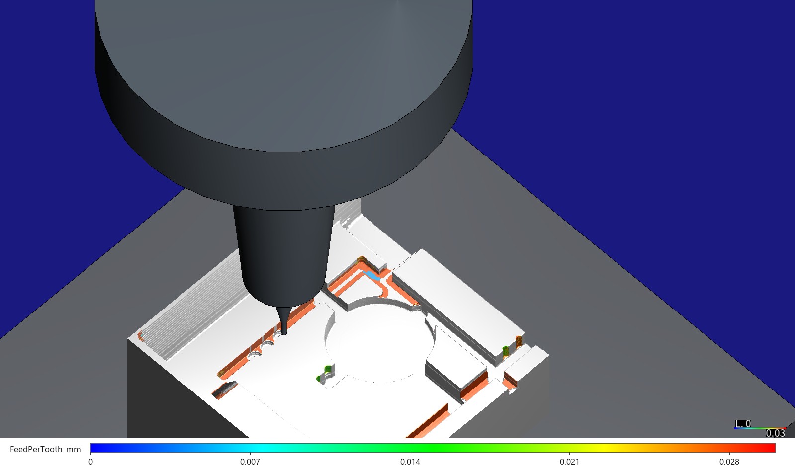
The trimmed B insert after HiNC's optimization of the Ø1 mm program, paused in the rib slot at Y 33 with the NS TOOL MHR230R Ø1 R0.1 end mill 18 mm out of a generic 4.5° shrink-fit chuck. The faces the Ø1 mm tool cut are coloured by the feed per tooth of the step that cut them, 0 to 0.03 mm: red and orange at the catalogue's 0.028 mm, one blue patch where the optimizer slowed into a corner. The same faces before the optimization are green, at the programmed 0.014 mm (further down). Captured on HiNC 3.2.45.
| Measured on HiNC 3.2.45 | Source programs | Optimized, replayed | Change |
|---|---|---|---|
| Whole B insert, simulated machining time, five programs (roughing and the Ø6 mm passes as accepted) | 719.97 min (12.0 h) | 474.00 min (7.9 h) | −34.2 % |
| Ø2 mm rest program (D2), whole insert | 180.40 min | 83.30 min | −53.8 % |
| Ø1 mm rib-slot program (D1), whole insert | 305.62 min | 156.75 min | −48.7 % |
| Where the 246 min come from: feed through air / cutting / rapids | — | — | −148.0 / −97.9 / 0 min |
| Largest tool stress ratio, D2 / D1 (target 0.333, a third of yield) | 1.05 / 1.07 | 0.91 / 0.70 | |
| Cutting steps at a stress ratio of 0.5 or more (the case's C2 (b)), D2 / D1 | 8 / 32 | 4 / 5 | |
| D1 XY tip deflection, 99th percentile / largest (the case's C3: 10 µm) | 19.5 / 78.5 µm | 22.3 / 51.8 µm | 10 µm not met either way |
| D2 XY tip deflection, 99th percentile / largest | 52.6 / 234.7 µm | 75.0 / 211.5 µm | |
| Final stock against the design, the case's own region-by-region check | — | — | every region the same as the source chain's |
| Trimmed patch, D2: the agent's hand corner rules against HiNC | 54.28 min, 1 step ≥ 0.5 | 20.61 min, 1 step ≥ 0.5 | the first program without the rules: 50.22 → 20.72 min, 124 → 1 |
| Trimmed patch, D1 with a 4.8 N target force for 10 µm | 52.26 min, p99 19.0 µm | 199.86 min, p99 11.9 µm | 10 µm not reached by feed |
| Whole-insert optimization plays, D2 / D1, on a shared 32-thread server | — | 30.2 / 56.6 min, 23.1 / 35.3 GB | replays 27.2 / 53.6 min, 10.1 / 15.7 GB |
The case
The mould's own case page tells how the agent derived the two inserts from the part, wrote its own CAM and played both inserts through an acceptance; this page starts where that one ends, on the B insert. What the agent was given:
- The B insert's five accepted programs: a Ø10 mm roughing (98.67 min), the Ø6 mm R0.5 semi-finishing (22.04 min) and finishing (113.24 min), the Ø2 mm rest program round the bosses, rib ends and corners (180.40 min) and the Ø1 mm program in the rib slots (305.62 min): 719.97 min, of which the two micro tools take 67 %.
- The micro tools, as the case built them from the maker's catalogue: T3, an NS TOOL MHR230R Ø2 R0.2 × 12, two flutes, 20 mm out of a generic 4.5° shrink-fit chuck, at 14,000 min⁻¹ and the catalogue's 1,500 mm/min (0.0536 mm per tooth, F-054), 750 mm/min in slots little wider than the tool and 375 mm/min into and out of corners, at the start of each pass and on links at depth — the rules the agent wrote when the tool met its previous level's corner head-on; T4, an MHR230R Ø1 R0.1 × 4, two flutes, 18 mm out, at 24,000 min⁻¹ (the spindle's limit; the catalogue's 25,000 min⁻¹ and 1,400 mm/min become 1,344) and the catalogue's halved slotting feed, 672 mm/min (0.014 mm per tooth, F-053), 336 on plunges.
- The case's criteria for these tools: C2 (b), every step of a rest tool under a stress ratio of 0.5; C3, the Ø1 mm tool's XY tip deflection in the rib slots at most 10 µm. The source programs miss both (8 and 32 steps at 0.5 or more; a 99th percentile of 19.5 µm).
- The case's set-up: a generic three-axis machine with 24 m/min rapids, the Showcase's generic 24,000 min⁻¹ spindle rated 7.5 kW continuous and 10 kW short-term, P20 with HiNC's shipped cutting data, each program played as its own run from the stock the previous one left.
- The request: showcases of HiNC's NC optimization built on existing cases, asked for by HiNC's product owner.
What nothing states:
- How fast the micro tools may go. The maker's catalogue gives a feed per tooth for each tool and halves it for slotting; nothing says when a slot cut is light enough for the full feed.
- How to hold a deflection limit. HiNC's optimizer holds spindle power, spindle torque, tool stress, thermal yield when it is switched on, a target force, any criterion a script registers, and the feed limits; it has no deflection criterion built in, so C3 has to be carried by another criterion.
- Whether HiNC sees the thinnest cuts. The Ø1 mm tool cuts 0.0275 mm per level, thinner than its 0.03125 mm mesh; a cut the stock model cannot see reads as air to the optimizer.
Every number on this page comes from this study's plays on HiNC 3.2.45: the optimization play of each source program is also its baseline, so each “before” was measured beside its “after”.
What the agent built
Each value is marked read (from the programs, the case or the catalogue), derived (computed from them), chosen (the agent's choice), default (HiNC's default, kept) or measured (in a play on HiNC 3.2.45).
A variant is one optimization play — HiNC plays the source program with an NC Optimization Config command before it and writes the optimized file after it — and one replay of the optimized file on the same project, stock, mesh and motion step. The trimmed patch is the case's own: a 54 × 46 mm piece of the B insert (X −112 to −58, Y −2 to 44) with a boss, its gussets, rib slots and the skirt wall.
| Play | On | What it answers |
|---|---|---|
| T0 | trimmed patch: roughing, semi-finishing and finishing as accepted, one run each | the stock the Ø2 mm tool starts from (18.57, 4.64 and 88.52 min, measured) |
| T1, T2 | the first 15,105 lines of the Ø2 mm first program; the first 6,015 lines of the Ø1 mm program | trials: does the optimizer change feeds in this program's dialect at a fixed motion step, does the replay run clean, how are plunges handled, what do the plays cost |
| V1-plain | trimmed patch, the Ø2 mm first program | can the optimizer find the corners without the hand rules |
| V1-hand | trimmed patch, the Ø2 mm accepted program, with the hand rules | what the optimizer does with the hand rules in place; its optimization play is also the hand rules' baseline |
| V2a | trimmed patch, the Ø1 mm program | HiNC's default targets and the catalogue ceiling, no deflection limit |
| V2b | the same | V2a plus a target force for C3 |
| V3 | the whole B insert | the Ø2 mm accepted program with V1's settings and the Ø1 mm program with V2a's (dilemma 4), each optimized, then both replayed in order; roughing and the Ø6 mm passes played as accepted to make the stock |
The Ø2 mm first program is the case's own CAM run again for the trimmed patch, the same Ø2 mm path written twice: once as the case writes it, which the agent checked is byte for byte the committed program, and once with only the first program's feed rules — 750 mm/min on each level's first loop, 1,500 elsewhere, 375 on plunges, 1,500 on links at depth — without the corner, start, link and narrow-slot slow-downs. The two programs are point for point the same path; planned at their feeds they take 50.3 and 54.3 min.
Each tool's optimization limits, sent whole through PUT api/Cutter/{id}/opt-limit before every
optimization play and read back into the run record: optimization on, yield safety factor 3 (the stress
held to a third of yield), the minimum-chip-thickness and relief-angle limits on, no minimum feed per
tooth — all default — and a feed-per-tooth ceiling equal to the catalogue's feed per tooth, read:
| Tool | Programmed feed per tooth — derived | Ceiling — read | Feed at the ceiling |
|---|---|---|---|
| T3 Ø2 R0.2, 2 flutes, 14,000 min⁻¹ | 0.0536 mm (F1500); 0.0268 mm in narrow slots (F750); 0.0134 mm into corners and on plunges (F375) | 0.05357 mm (F-054: 1,500 ÷ (14,000 × 2)) | 1,500 mm/min |
| T4 Ø1 R0.1, 2 flutes, 24,000 min⁻¹ | 0.014 mm (F672); 0.007 mm on plunges (F336) | 0.028 mm (F-053: 1,400 ÷ (25,000 × 2)) | 1,344 mm/min |
The catalogue's feed is the maker's recommendation for the tool; its slotting half and the agent's corner rules are general allowances for the worst cut. The study lets the optimizer replace those allowances with the loads it reads: where a cut is light, the feed may rise to the catalogue's; where it is heavy, the stress criterion (and in V2b the target force) brings it down.
The NC Optimization Config before every program, every key written out and read back:
| Setting | Value | Source |
|---|---|---|
| Feed optimization, re-interpolation | on | default |
| Max feed per tooth | 0.05357 mm (D2), 0.028 mm (D1) | read: the ceilings above |
| Min feed per tooth | 0 | default: the physical lower bound is the tool's minimum-chip-thickness limit |
| Min feedrate | 30 mm/min | chosen: an order of magnitude under the lowest programmed feed (the Ø1 mm plunge, 336); the default 1 mm/min would let one phantom reading stall a stretch at almost nothing |
| Max feedrate | 20,000 mm/min | chosen: under the machine's 24,000 mm/min rapids; the ceiling per tooth acts first |
| Rapid Feed — the air feed, for lines with no cutting within the extended distances | 1,500 mm/min (D2), 1,344 mm/min (D1) | chosen: each tool's ceiling feed, not a high-speed air feed (dilemma 6) |
| Max acceleration | 1,000 mm/s² | chosen: the default 10 mm/s² would spread every change of feed over hundreds of millimetres |
| Lower limit as a share of the source feedrate | off (0.8 if on) | default: the study asks how far the optimizer itself slows the corners |
| Spindle power and torque safety factors | 1.5: the target is 67 % of the short-term rating | default (the micro tools use about 1 % of the spindle) |
| Yielding safety factor of the command | 0: the tool's own factor 3 holds | default |
| Thermal yield safety factor | 0: not a criterion | default |
| Preferred force (the target cutting force) | none (Infinity); in V2b 4.8 N for the Ø1 mm program |
default; derived (V2b, below) |
| Extended pre and post distance | 2 mm and 2 mm | default |
| Feedrate assignment ratio | 0.01 | default |
| Forward, side and depth compensation; depth splitting | off | chosen: compensation is not part of this study; with depth splitting off, a step the target force pins at the minimum is logged at the minimum |
| Omit leading zero | off | chosen: the agent's checks read every number of the output |
V2b's target force = the C3 limit ÷ the Ø1 mm tool's compliance = 10 µm ÷ 2.084 µm/N = 4.8 N, derived. The compliance is the 95th percentile, over V2a's source cutting steps (in contact, removing more than 0.01 mm³/s, more than 0.5 N), of XY tip deflection ÷ largest cutting force; at that target 95 % of the steps stay within 10 µm. Deflection here is HiNC's tool-beam model; the target holds the model's deflection, not a measured one. The Ø2 mm tool has no deflection criterion in the case and gets no target force: its deflection is only compared with the first program's (O5).
Mesh and motion step, as the case accepted them, read: 0.0625 mm for the Ø2 mm tool, 0.03125 mm for the Ø1 mm tool, 0.25 mm for roughing and semi-finishing, 0.125 mm for finishing; a fixed motion step of 1.0 mm for roughing and 0.4 mm for every other program, rapids stepped the same way. One program per run: each run reads the stock the previous program left from a file and writes its own, so the optimization sees the loads the acceptance judged.
Not optimized: the roughing and the Ø6 mm passes, played as accepted only to make the stock; rapids,
tool changes and the G43 lines, which the optimizer never changes. The programs have no canned cycles,
arcs or cutter compensation.
Plunges, a rule written before the plays: if a trial wrote the plunges (G01 moving Z only) below
half the programmed plunge feed (Ø2 mm under 187.5, Ø1 mm under 168 mm/min), set by stress or force
rather than the relief angle or the minimum chip thickness, and HiNC's removal on those steps exceeded
twice what the agent's exact stock allows (a phantom plunge reading), then every plunge of every variant
would be held at its programmed feed with a (@@Preserve();) script comment; otherwise the plunges are
optimized like any line.
The air-feed guard, the agent's own check after every optimization: the optimized program walked over the CAM's exact stock of that program (a 0.05 mm height field, its margins on the side of more stock, lowered as the program goes), each feed move's depth before it cuts compared with the feed written and with HiNC's contact on that line.
How the agent managed the work
- Criteria and settings first. The plan — eight criteria, every setting with its source, the plunge rule and the condition for the whole-insert variant — was committed before the first optimization play. What the plays changed was written beside it three times — after the trials and after V1 and V2, each before the next play, and after V3 — and the criteria were never rewritten.
- Small before large. Two trials on the first lines of each micro program checked the whole chain — optimize, replay, check that the feeds really changed and that the replay runs every line clean — before any full program; the trimmed patch carried every variant before the whole insert.
- One heavy play at a time. A private copy of HiNC 3.2.45 ran on a 32-thread server shared with live services and other agents' studies. Every play queued on a lock shared with those studies and ran with the project closed and reloaded from its file, and a read-only check every three minutes looked at the alarms, the line reached, the contact and the loads.
- Settings read back. Each tool's limits and every option were read back after each play and kept with its results, beside the messages, the server time and the memory.
- Decisions fixed before the result. The plan made V3 conditional on V1's and V2b's replays passing O1, O2, O6 and O7. When V2b failed O2, the agent wrote down, before the whole insert's Ø1 mm play, that V3's Ø1 mm program would take V2a's settings instead, and why (dilemma 4).
- The study changed hands once. The first agent stopped while the whole insert's last replay was running on the server; the agent that took over watched that replay read-only to its end rather than start it again, and wrote the readings it added after the plays beside the plan.
- Where a person stepped in. HiNC's product owner asked for NC-optimization showcases built on existing cases; the variants, settings and criteria are the agent's.
The criteria as written before the first optimization play. A cutting step is a step in contact that removes more than 0.01 mm³/s:
| # | Criterion |
|---|---|
| O1 | Every optimized program replays to its last line with no new alarm: the lines run equal the file's; no warning or error the baseline (the same program's optimization play) lacks, and no new kind of Collided(...), Play-RapidCut--* or stroke alarm; of a kind the baseline has, no more than 1.1 times its count plus 2 |
| O2 | The governing loads within target: at least 99 % of the replay's cutting steps at a stress ratio of at most 0.34 (0.333 × 1.02) and at most 0.68 of the spindle's short-term power and torque; for the Ø1 mm tool with a target force, the largest force at most the target × 1.02. Peaks and places listed: a replay may read slightly higher, its interpolation points being different |
| O3 | The shape does not change: the replay's exported stock against the baseline's, column by column on a 0.05 mm grid, at least 99.9 % of the cut columns within one mesh width; V3 also against the design by the acceptance's own method |
| O4 | The expected time: V1-plain's replay no longer than the hand-ruled program's baseline (the optimizer no dearer than the hand rules); V1-hand no longer than that baseline; V2a at most 0.80 of its baseline; V2b no longer than its baseline; V3, the whole insert's five programs, shorter than the source's |
| O5 | Deflection: the Ø1 mm tool (V2b, V3) a 99th percentile of at most 10 µm (C3), V2a listed; the Ø2 mm tool (V1-plain, V1-hand) a 99th percentile and largest step at most the first program's × 1.02 + 1 µm |
| O6 | The air feed never lands on stock: the guard finds no feed move that cuts (more than 0.005 mm) at a feed above the tool's ceiling × 1.02; each program's contact path within ±3 % of the baseline's |
| O7 | The output really is optimized: each optimized file differs from its source; the optimization reports Optimization Feedrate built. and Total 1 files optimized.; no StepFailed; the program-manipulation messages listed |
| O8 | The case's C2 (b): every replayed cutting step of the Ø2 mm and Ø1 mm tools under a stress ratio of 0.5 (the source programs on the whole insert: 8 and 32 steps at 0.5 or more) |
The dilemmas
Each is told as its situation, the risk had it been missed, how it was noticed, the resolution, and the evidence that the resolution held.
1. Most of the time saved is feed through air
- Situation. In the first trial the Ø2 mm stretch fell from 8.53 to 6.14 min, but its time in contact grew, 3.05 to 3.66 min: the gain was in moves that touch nothing. The agent's CAM starts every loop of a level 1 mm above the stock as it stood before the program and descends at the plunge feed, on a 3° ramp 19 times as long as it is deep or straight down, so on the deep levels most of that descent runs through levels already cut; in the trial's stretch the straight plunges alone took 3.92 of its 8.53 min (46 %). On the whole insert, by the agent's count of the program, the Ø2 mm program spends 101 min on such ramps and 15 min on straight plunges.
- Risk. A reader takes the saved time for faster cutting, or credits the optimizer with what a shorter link in the CAM would also give.
- How noticed. The agent's split of every step's time into cutting (HiNC reads contact), feed through air and rapids.
- Resolution. Every time on this page is split those three ways. The optimizer sends a feed move on which HiNC reads no stock, within the extended distances, at the air feed — here the ceiling's feed — so the ramps through cut levels go from 375 to 1,500 mm/min. That is part of what the optimization gives on this program, but not a faster cut, and a CAM that started each loop at the level just cut would save most of it without any optimization.
- Evidence. On the whole insert, of the 246 min saved: feed through air 148.0 min (D2 124.71 → 35.29, D1 91.71 → 33.08), cutting 97.9 min (D2 43.91 → 36.23, D1 196.64 → 106.40), rapids unchanged (11.77 and 17.27). On the trimmed patch the chart below; the full split is under Results and benefits.
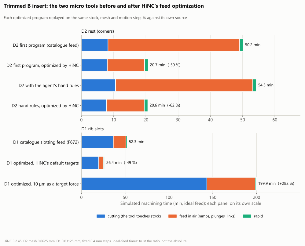
The trimmed patch: each micro program before and after, split into cutting, feed through air (ramps, plunges, links) and rapids. The Ø2 mm programs lose most of their air time; the Ø1 mm program with HiNC's default targets halves its cutting time.
2. The optimizer against the agent's hand rules
- Situation. In the case the Ø2 mm tool read a stress ratio over 0.5 at the points where it met the corner its previous level had left, head-on, and the agent wrote feed rules to slow it there (the case page tells them). On the same path those rules cost 8 % more time: 50.22 → 54.28 min on the trimmed patch. Would the optimizer have found those places by itself?
- Risk. Keeping rules the optimizer makes unnecessary; or trusting the optimizer where the rules caught something it does not.
- How noticed. The plan's question, answered with the two programs of the same path (V1-plain and V1-hand).
- Resolution. From either program HiNC writes nearly the same feeds: 20.72 and 20.61 min, each with a single step at 0.5 or more, at the same slot end (dilemma 3). From the first program, the 124 steps at 0.5 or more fall to 1 and the 1,076 over 0.34 — the target with O2's 2 % margin — to 5. The optimizer slows where the stress rises and runs the catalogue's 1,500 mm/min elsewhere, also on many steps the hand rules had slowed; so its 99th-percentile stress (0.332) and tip deflection (75.0 µm) sit above the hand-ruled program's (0.218 and 50.0 µm), within its target, while its largest steps stay below the first program's.
- Evidence.
| Trimmed patch, Ø2 mm program | First program | First program, optimized | Hand rules (accepted program) | Hand rules, optimized |
|---|---|---|---|---|
| Simulated time | 50.22 min | 20.72 min (−58.7 %) | 54.28 min | 20.61 min (−62.0 %) |
| Cutting / feed through air / rapids | 8.24 / 40.86 / 1.11 min | 8.03 / 11.58 / 1.11 min | 10.60 / 42.57 / 1.11 min | 7.84 / 11.66 / 1.11 min |
| Cutting steps | 35,071 | 35,123 | 40,213 | 40,523 |
| Stress ratio, median / 99th percentile / largest | 0.105 / 0.442 / 1.025 | 0.101 / 0.332 / 0.941 | 0.088 / 0.218 / 0.618 | 0.099 / 0.332 / 0.904 |
| Cutting steps over 0.34 / at 0.5 or more / at 1 or more | 1,076 / 124 / 1 | 5 / 1 / 0 | 23 / 1 / 0 | 3 / 1 / 0 |
| Largest force, 99th percentile / largest | 43.1 / 101.8 N | 32.3 / 95.1 N | 21.1 / 62.1 N | 32.3 / 91.4 N |
| XY tip deflection, median / 99th percentile / largest | 23.8 / 99.8 / 232.3 µm | 22.9 / 75.0 / 220.1 µm | 19.9 / 50.0 / 144.6 µm | 22.4 / 75.0 / 211.4 µm |
| Cutting feed, time-weighted, 5th / 50th / 95th percentile | 375 / 1,500 / 1,500 | 168 / 1,500 / 1,500 | 375 / 375 / 1,500 | 145 / 1,500 / 1,500 mm/min |
| Spindle power, short-term rating, largest | 0.014 | 0.017 | 0.012 | 0.017 |
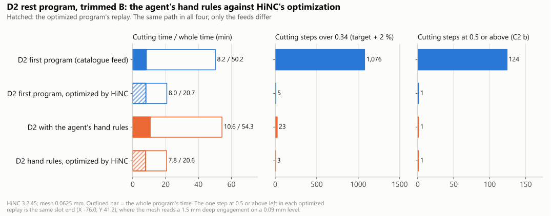
The same Ø2 mm path in four versions. Left: cutting time inside the whole time; hatched, the optimized programs' replays. Middle and right: the cutting steps over 0.34 (the 0.333 target plus 2 %) and at 0.5 or more.
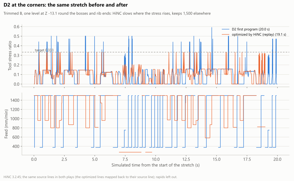
One level of the Ø2 mm program on the trimmed patch, Z −13.1, before and after. The first program holds 1,500 mm/min through the corners and peaks at 0.6; the optimized one slows where the stress rises and keeps 1,500 elsewhere, in 19.1 s against 20.0 s.
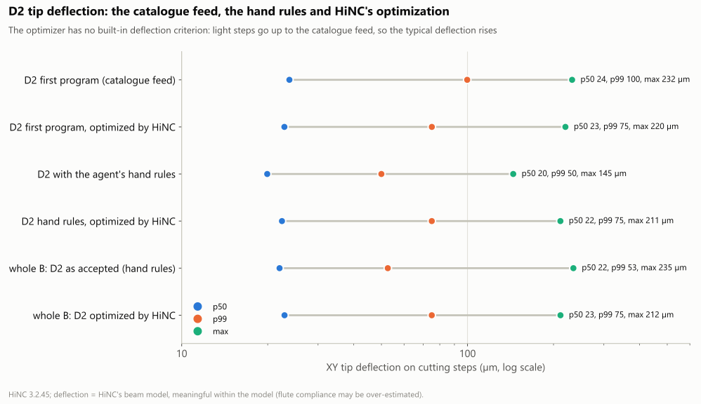
The Ø2 mm tool's XY tip deflection on its cutting steps: the median and the largest change little; the 99th percentile sits at 75 µm after any optimization, between the hand rules' 50 µm and the catalogue feed's 100 µm.
3. One slot end that a replay reads high
- Situation. O8 asks every replayed cutting step under a stress ratio of 0.5. Each optimized Ø2 mm program kept one step over it on the trimmed patch, 0.94 and 0.90, both at the slot end X −76.0, Y 41.2 (Z −15.70 and −15.75), where the 0.0625 mm mesh reads a 1.5 mm deep engagement and a removal of 20 mm³/s on a 0.09 mm level.
- Risk. Reading the optimizer as ignoring its target, or dismissing the target for one step.
- How noticed. O8, and the same slot end in the optimization play and the replay.
- Resolution. In the hand-ruled source program the heavy step at that slot end is on the level above, at Z −15.66 (0.62). The optimizer wrote it at its 30 mm/min minimum; in the replay that step reads 0.43, and the heavy reading appears instead on the next level down, 0.90 at 765 mm/min, where the optimization play had read at most 0.36. A re-interpolated feed moves the points at which HiNC samples the cut, and the reading moves with them; NC Optimization says a replay's loads can sit slightly above the targets for this reason. O8 is reported as not met, by one step in each program.
- Evidence. On the whole insert the Ø2 mm replay keeps 4 steps at 0.5 or more (the source program 8): three at the slot ends at Y 41.2 (X 74.9 at 0.91 and 0.82, X −76.0 at 0.90) and one at X 88.1, Y 21.2 at 0.52; 9 of its 183,415 cutting steps are over 0.34.
4. A target force that no feed can reach
- Situation. The case's C3 asks the Ø1 mm tool's XY tip deflection in the rib slots to stay within 10 µm; the source program reads a 99th percentile of 19.0 µm on the trimmed patch. V2b carried C3 as a target force of 4.8 N.
- Risk. A variant that misses its target by a wide margin at a large cost in time, with settings that look as if they hold the limit.
- How noticed. O2, O4 and O5 on V2b's replay, and the optimizer's per-step log.
- Resolution. V2b took the trimmed Ø1 mm program from 52.26 to 199.86 min (+282 %). 3,594 cutting steps, 5.5 %, cannot get under 4.8 N even at 30 mm/min: in the source program they read a median of 7.7 N, remove 3.6 times as much per step as the others, and HiNC's force on them barely falls with the feed. The optimizer writes them, with 2 mm before and after each, at its minimum: 990 stretches at F30, and the replay spends 173 of its 200 min below 60 mm/min. Its 99th percentile is 11.9 µm, still over 10 µm; O2 (92.7 % of its cutting steps at or under 4.9 N), O4 and O5 are not met. Within HiNC's model, C3 is out of reach of the feed. The plan allowed V3 only after V2b's replay had passed O1, O2, O6 and O7; the agent wrote down instead, before the whole insert's Ø1 mm play, that V3's Ø1 mm program would take V2a's settings — HiNC's default targets and the catalogue ceiling — because V2a's replay met every criterion it could be judged on and the whole insert's time is the case's main number, and that O5 would be reported as not met.
- Evidence.
| Trimmed patch, Ø1 mm program | Source (F672) | V2a: HiNC's default targets | V2b: target force 4.8 N |
|---|---|---|---|
| Simulated time | 52.26 min | 26.44 min (−49.4 %) | 199.86 min (+282 %) |
| Cutting / feed through air / rapids | 36.40 / 14.53 / 1.33 min | 19.84 / 5.27 / 1.33 min | 143.30 / 55.21 / 1.33 min |
| Cutting steps | 65,041 | 66,337 | 55,228 |
| Stress ratio, median / 99th percentile / largest | 0.089 / 0.285 / 0.480 | 0.098 / 0.331 / 0.333 | 0.097 / 0.172 / 0.332 |
| Largest force, 99th percentile / largest | 9.25 / 16.78 N | 10.70 / 12.55 N | 5.91 / 11.38 N |
| Cutting steps at or under 4.9 N | — | 88.1 % | 92.7 % |
| XY tip deflection, median / 99th percentile / largest | 5.9 / 19.0 / 34.4 µm | 6.4 / 22.0 / 25.0 µm | 6.3 / 11.9 / 23.1 µm |
| Cutting steps within 10 µm | 93.6 % | 90.1 % | 94.4 % |
| Cutting feed, time-weighted, 5th / 50th / 95th percentile | 672 / 672 / 672 | 461 / 1,344 / 1,344 | 30 / 30 / 1,344 mm/min |
In V2b's replay the steps slowed to 30 mm/min with little contact fall under the 0.01 mm³/s that makes a cutting step, which is why it counts fewer cutting steps than the source.
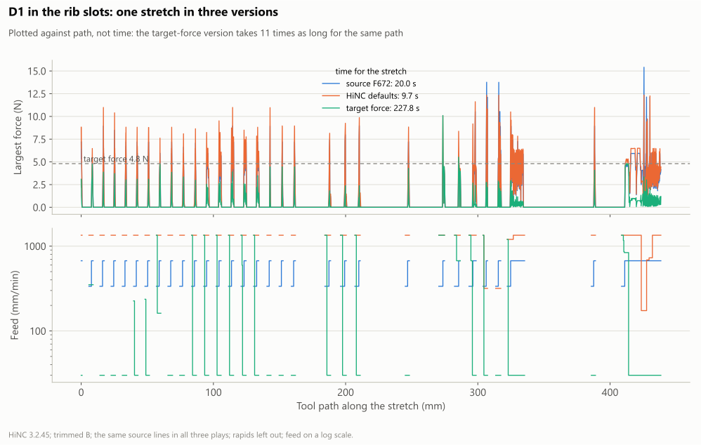
One stretch of the Ø1 mm program on the trimmed patch, drawn against the tool path rather than time: the source at F672 takes 20.0 s, HiNC's default targets 9.7 s, the target force 227.8 s for the same path.
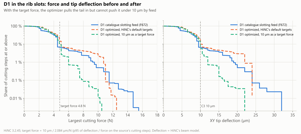
The Ø1 mm tool's force and XY tip deflection on the trimmed patch, the share of cutting steps at or above each value. The target force pulls the tail in but does not bring it under 10 µm.
5. Three tooth tips that read over 1
- Situation. Beside the plateau on the whole B insert stands a row of 1 mm teeth at a 3 mm pitch, at X 65.1 with its top at Z −13.09. The source Ø1 mm program reads its three largest stress ratios at three V-shaped tips, Y 22.8, 13.8 and 4.7: 1.05, 1.07 and 1.05 at F672, where HiNC reads the whole 0.8 mm flute engaged on the tooth and 40.8–42.1 N.
- Risk. A program sent at a feed that breaks the tool by HiNC's reading, or a whole program slowed for three steps.
- How noticed. The whole insert's source play, where these are the tool's peak steps, and the optimizer's per-step log at those steps.
- Resolution. At the three tips the log gives the tool-stress criterion's feed as the minimum, 0.000625 mm per tooth (30 mm/min): even there the stress ratio stays above a third. The 2 mm extended distance covers each tooth's whole pass, a plunge and 14 lines of contour about 1.6 mm long, so each of the three passes is written at F30, 22.4 times slower, while the other teeth go to the 1,344 mm/min ceiling. The replay reads 0.69–0.70 at the tips (27.2–27.9 N): HiNC's force there falls only 1.5 times for 22.4 times less feed. The row of teeth played on its own shows the same — without the Ø1 mm program's earlier passes its readings run higher, 1.38 at a tip — at 22.4 times less feed per tooth the force falls 1.5–1.8 times (about the 0.13th to 0.19th power of the feed per tooth), and doubling the feed on the flat-topped teeth raises it 1.2–1.35 times. The real engagement at a V-tip was not computed exactly; the reading there may be high, as at the corners met head-on in the case. On the whole insert ten stretches are written at F30 — these three teeth and seven slot ends near X ±66, Y −31 to −36 and at (−41.7, −36.5) — and the replay's feed moves spend 1.8 min below 60 mm/min, 32 s of it on cutting steps.
- Evidence.
| Whole insert, the row of teeth (source lines 64,376–64,516) | Source (F672) | Optimized, replayed |
|---|---|---|
| Time for the stretch | 3.1 s | 17.3 s |
| Steps in contact | 39 | 39 |
| Largest stress ratio | 1.072 | 0.701 |
| Steps over 0.34 / at 0.5 or more / at 1 or more | 3 / 3 / 3 | 3 / 3 / 0 |
| Feed on the steps in contact: lowest / median / highest | 672 / 672 / 672 | 30 / 1,344 / 1,344 mm/min |
| Largest force / largest XY tip deflection | 42.1 N / 78.5 µm | 27.9 N / 51.8 µm |
| Tip at Y 22.8 / 13.8 / 4.7: stress ratio | 1.047 / 1.072 / 1.047 | 0.686 / 0.701 / 0.686, each at F30 |
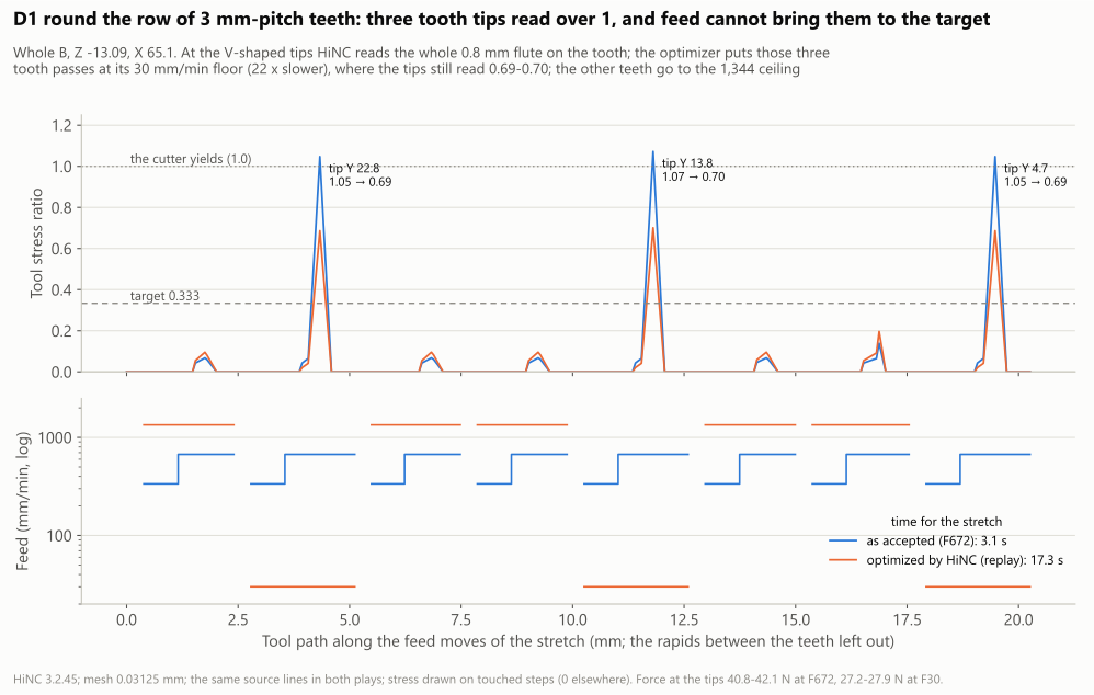
The whole insert's Ø1 mm program round the row of teeth. The optimizer puts the three tooth passes at its 30 mm/min minimum and the others at the ceiling; the tips still read 0.69–0.70.
6. An air feed that must be safe on a cut the grid cannot see
- Situation. The optimizer sends a line with no cutting within the extended distances at the air feed. The Ø1 mm tool cuts 0.0275 mm per level on a 0.03125 mm mesh, the Ø2 mm tool 0.09 mm on a 0.0625 mm mesh: HiNC's stock can miss a thin cut, and the optimizer then reads it as air.
- Risk. A cut sent at a high air feed, and a micro tool broken.
- How noticed. In the plan, before any play.
- Resolution. Each tool's air feed is its ceiling feed, 1,500 and 1,344 mm/min, not a high-speed air feed. A cut HiNC cannot see is at most one mesh width (D2) or one level (D1) deep across the slot; at the ceiling its chip section per tooth is 0.0034 mm² (D2) and 0.00077 mm² (D1), under the catalogue's own side-milling sections, 0.0042 and 0.0015 mm². The guard checks every feed move of every optimized program against the exact stock.
- Evidence. In every variant no feed move cuts at a feed above the ceiling × 1.02, and no line HiNC read as air has stock under the inner half of the tool. The lines HiNC read as air that do cut, at the tool's rim, are 8–16 % of the cutting length, at a median depth of 0.04 mm for the Ø2 mm tool and one 0.0275 mm level for the Ø1 mm tool (table under Results and benefits); the Ø1 mm trial had already found 605 such lines, 21 % of its cutting length, at a median of exactly one level. The price: the air feed is no higher than the ceiling, so less is saved than a high-speed air feed would allow.
7. Steps that remove stock with no force read
- Situation. 1.4–5.4 % of the cutting steps remove stock in HiNC's model while it reads no force on them; for those the optimizer's log carries only the relief-angle row, and they get the ceiling.
- Risk. A step that cuts more than HiNC reads, sent at the ceiling.
- How noticed. The per-step log, step by step.
- Resolution. Counted apart in the results, as “no load read”. The ceiling is the maker's catalogue feed per tooth, so such a step runs at most at the catalogue's condition: that is why every ceiling on this page has a source.
- Evidence. The limits chart and table under Results and benefits: 5.4 % of the Ø2 mm first program's cutting steps, 4.6 % of the hand-ruled one's, 1.4 % of the Ø1 mm program's, 3.8 % and 3.0 % on the whole insert.
8. A step length that spans two steps
- Situation. At a fixed motion step, a step record's path length (
MovingLength_mm, andMoveOnProgramCoordinate) on the second and later steps of a line is the displacement over the last two steps. The agent's first analysis summed it into each program's path and contact length. - Risk. Path lengths about 1.9 times too long, and O6's contact-path comparison judged on them.
- How noticed. A check of those lengths against the distance between the tool positions: a ratio of 2.0 on a large share of the steps (68 % of the whole insert's Ø1 mm feed steps over 1.5).
- Resolution. A minimal program shows it: one 2 mm
G01at F600 in 0.4 mm steps reads 0.4, 0.8, 0.8, 0.8 and 0.8 mm, and the next 1 mm line in steps of 0.333 mm reads 0.333, 0.667 and 0.667 mm. The step's duration is right, so the times are unaffected. The analysis takes each step's length from the distance between successive tool positions, and every summary was recomputed; O6's verdicts did not change. The optimizer's acceleration limit reads the same field, so on straight lines it allows up to twice the acceleration set; at the 1,000 mm/s² set here the effect is small. - Evidence. The whole insert's Ø2 mm feed path from the tool positions is 94,881 mm, the length the guard's walk of the program gives; the step records' field sums that program's whole path to 728.9 m against 382.8 m.
9. Single columns 1.8 mm apart
- Situation. O3 compares the replay's exported stock with the baseline's column by column; in every Ø2 mm variant and on the whole insert a few columns differ by up to 1.4–1.8 mm.
- Risk. A changed shape taken for noise, or the reverse.
- How noticed. O3's largest difference.
- Resolution. The columns more than one mesh width apart were split into walls — where the design height changes by more than 0.2 mm within 3 × 3 cells, the acceptance's own steep-face rule — and flat ground. Every one lies on a wall, where a column beside the wall reads its top or its foot depending on a sub-cell shift; on flat ground none is a mesh width apart.
- Evidence. The shape table under Results and benefits: 0.0025–0.175 mm² outside one width, all on walls; the removed volume equal to within 0.013 mm³.
10. A reference that exists only on the trimmed patch
- Situation. O5 judges the Ø2 mm tool's deflection against the first program at the catalogue feed; only the trimmed patch played that program, and the whole insert has only the accepted, hand-ruled one.
- Risk. Judging the whole insert against no reference, or against another one without saying so.
- How noticed. When judging V3.
- Resolution. The whole insert's Ø2 mm replay is judged against the accepted program: not met, its 99th percentile 52.6 → 75.0 µm, its largest step 234.7 → 211.5 µm. The trimmed patch's catalogue-feed readings, 99.8 and 232.3 µm, are listed beside it.
- Evidence. The criteria table.
11. A comparison with the design written without a tolerance
- Situation. The plan said V3 would also be judged against the design by the acceptance's method, but gave no tolerance for that comparison.
- Risk. A verdict whose bar is chosen after the result.
- How noticed. When judging V3.
- Resolution. The bar was written down beside the plan after the play: per region, the area left more than 0.1 mm above the design and the area cut more than 0.0625 mm below it no more than 0.5 mm² above the source chain's, and the median within 0.005 mm.
- Evidence. The two chains read the same in every region to 0.01 mm² and 0.0001 mm (the design table under Results and benefits).
12. The smaller ones
| What happened | Risk | How it showed | Resolution | Evidence it held |
|---|---|---|---|---|
| The plunge rule written before the plays | plunges held for nothing, or slowed by a phantom reading | the two trials | the plunges in contact were set by the relief angle (54 and 167 steps) or the ceiling (17 and 84), 4 of the Ø1 mm trial's by stress; the slowest written F271 (D2) and F232 (D1), above half the programmed plunge feed (187.5 and 168), so the rule did not apply and the plunges were optimized | the trials' optimized programs, read line by line |
| HiNC's default minimum feed is 1 mm/min | one phantom reading stalls a stretch | the plan | the minimum set to 30 mm/min | the slowest feed written is 30 mm/min |
| The first agent stopped while the whole insert's Ø1 mm replay was running | a heavy play run twice, or killed halfway | the server's process list | the agent that took over watched it read-only to the end | the replay ran every line, 3,213 s |
| A picture play queued by the first agent paused with no one to photograph it | a held lock and no picture | the paused play's record | queued again | the four canvas pictures on this page |
| A paused play runs on a few dozen lines before it stops | a before and an after 20 mm apart | the first pair | both programs cut off at the same source line (the optimized one at the line that carries that line's note) and played to their end | both end at X −85.675, Y 33.225, under one camera |
| The tooth faces the Ø1 mm tool cut showed no colour from any preset view | no picture of the teeth | the exploratory shots | no teeth picture; the trace chart tells it, and the pose's step records serve as the row-of-teeth play of dilemma 5 | the chart under dilemma 5 |
| A re-analysis dropped the target force from two replays' statistics (a replay carries no option of its own) | O2 for the target force judged without it | the final check of the criteria | the target passed to the analysis again | 88.1 % and 92.7 % at or under 4.9 N, as first measured |
| Four picture plays shared the lock with another agent's study | a study's tail never getting its turn | the queue | each pause photographed and the lock released within 15 min | the pictures and both studies' plays |
| A trimmed-patch play needs more than the 1.5 GB under which a play may skip the shared lock (the first trial sampled 2.8 GB) | two heavy plays at once on the shared server | the first trial's memory | every trimmed-patch play queued on the lock, as the plan said | the queue record of every play |
Results and benefits
Measured on HiNC 3.2.45: the trimmed patch at the case's mesh widths, every variant optimized and replayed; the whole B insert with the roughing and the Ø6 mm passes as accepted and both micro programs optimized and replayed, one program per run. Times are HiNC's ideal-feed estimates; the agent's own arithmetic from the programs, path over feed plus rapids at 24 m/min, agrees with them within 0.25 % (D2 180.59 and 83.49 min, D1 305.91 and 157.04 min against HiNC's 180.40, 83.30, 305.62 and 156.75).
The criteria, per variant:
| # | V1-plain (D2 first program) | V1-hand (D2 hand rules) | V2a (D1, default targets) | V2b (D1, target force) | V3, D2 (whole) | V3, D1 (whole) |
|---|---|---|---|---|---|---|
| O1 | met: 98,958 of 98,958 lines, no message | met: 109,664 lines | met: 38,521 lines | met: 40,638 lines | met: 360,241 lines; 2 rapid grazes and 3 shank flags, as in the source play | met: 243,178 lines; 3 rapid grazes and 48 shank flags, as in the source play |
| O2 | met: 99.986 % within 0.34; power ratio at most 0.017 | met: 99.993 % | met: 100 % | not met: 92.7 % at or under 4.9 N (stress 100 %) | met: 99.995 % | met: 99.997 % |
| O3 | met: 99.986 % of columns within 0.0625 mm | met: 99.984 % | met: 100 % within 0.03125 mm | met: 99.999 % | met: 99.990 % | met: 99.984 %; against the design, every region as the source chain's |
| O4 | met: −58.7 %, and 20.72 min under the hand rules' 54.28 | met: −62.0 % | met: −49.4 % (at most −20 % asked) | not met: +282 % | whole insert met: −34.2 % | whole insert met: −34.2 % |
| O5 | met: p99 99.8 → 75.0 µm, largest 232.3 → 220.1 µm | met: p99 75.0, largest 211.4 µm against the first program's | listed: p99 19.0 → 22.0 µm, largest 34.4 → 25.0 µm | not met: p99 11.9 µm | not met against the accepted program: p99 52.6 → 75.0 µm, largest 234.7 → 211.5 µm | not met: p99 19.5 → 22.3 µm (C3 10 µm), largest 78.5 → 51.8 µm |
| O6 | met: no move above the ceiling; contact path +0.02 % | met: −0.01 % | met: 0.00 % | met: 0.00 % | met: −0.01 % | met: 0.00 % |
| O7 | met: the file differs; feed built; 1 file optimized; no program-manipulation message | met | met | met | met | met |
| O8 | not met: 1 step at 0.94 (the source 124) | not met: 1 step at 0.90 (the source 1) | met: 0 | met: 0 | not met: 4 steps (the source 8) | not met: 5 steps (the source 32) |
The whole B insert, program by program:
| Whole B insert | Roughing Ø10 | Semi-finishing Ø6 | Finishing Ø6 | D2, source | D2, optimized | D1, source | D1, optimized |
|---|---|---|---|---|---|---|---|
| Simulated time | 98.67 min | 22.04 min | 113.24 min | 180.40 min | 83.30 min | 305.62 min | 156.75 min |
| Cutting / feed through air / rapids, min | 49.55 / 48.87 / 0.24 | 17.23 / 4.31 / 0.49 | 98.32 / 13.59 / 1.34 | 43.91 / 124.71 / 11.77 | 36.23 / 35.29 / 11.77 | 196.64 / 91.71 / 17.27 | 106.40 / 33.08 / 17.27 |
| Plunges, min (included above) | 0.03 | 0.59 | 2.43 | 15.33 | 4.80 | 67.16 | 20.32 |
| Steps / cutting steps | 121,065 / 54,047 | 91,355 / 54,293 | 345,495 / 243,838 | 1,200,719 / 182,262 | 1,200,806 / 183,415 | 1,638,058 / 365,933 | 1,638,164 / 372,493 |
| Stress ratio, median / p99 / largest | 0.160 / 0.409 / 0.518 | 0.128 / 0.512 / 0.974 | 0.024 / 0.084 / 0.506 | 0.097 / 0.232 / 1.052 | 0.101 / 0.332 / 0.909 | 0.090 / 0.287 / 1.072 | 0.098 / 0.331 / 0.701 |
| Steps over 0.34 / at 0.5 or more / at 1 or more | 836 / 124 / 0 | 1,797 / 643 / 0 | 35 / 1 / 0 | 456 / 8 / 1 | 9 / 4 / 0 | 1,528 / 32 / 3 | 10 / 5 / 0 |
| Largest force, p99 / largest | 741.6 / 946.8 N | 332.7 / 681.5 N | 53.3 / 329.8 N | 22.5 / 108.7 N | 32.3 / 91.7 N | 9.5 / 42.1 N | 10.9 / 27.9 N |
| XY tip deflection, median / p99 / largest | 24.4 / 60.7 / 76.8 µm | 19.4 / 76.6 / 153.9 µm | 3.6 / 12.6 / 77.4 µm | 22.0 / 52.6 / 234.7 µm | 22.9 / 75.0 / 211.5 µm | 6.0 / 19.5 / 78.5 µm | 6.4 / 22.3 / 51.8 µm |
| Cutting steps within 10 µm | — | — | — | 20.2 % | 18.1 % | 92.7 % | 89.7 % |
| Spindle power, largest, of the short-term (continuous) rating | 0.564 (0.752) | 0.110 (0.146) | 0.036 (0.047) | 0.012 (0.017) | 0.018 (0.025) | 0.007 (0.009) | 0.004 (0.005) |
| Cutting feed, time-weighted, 5th / 50th / 95th percentile, mm/min | 275 / 900 / 900 | 750 / 750 / 1,500 | 750 / 750 / 1,500 | 375 / 1,500 / 1,500 | 271 / 1,500 / 1,500 | 672 / 672 / 672 | 615 / 1,344 / 1,344 |
| Program lines | — | — | — | 357,989 | 360,241 | 235,960 | 243,178 |
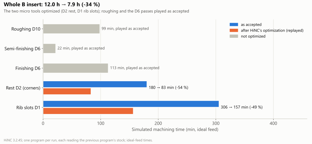
The whole B insert, 12.0 → 7.9 h. Only the two micro programs were optimized.
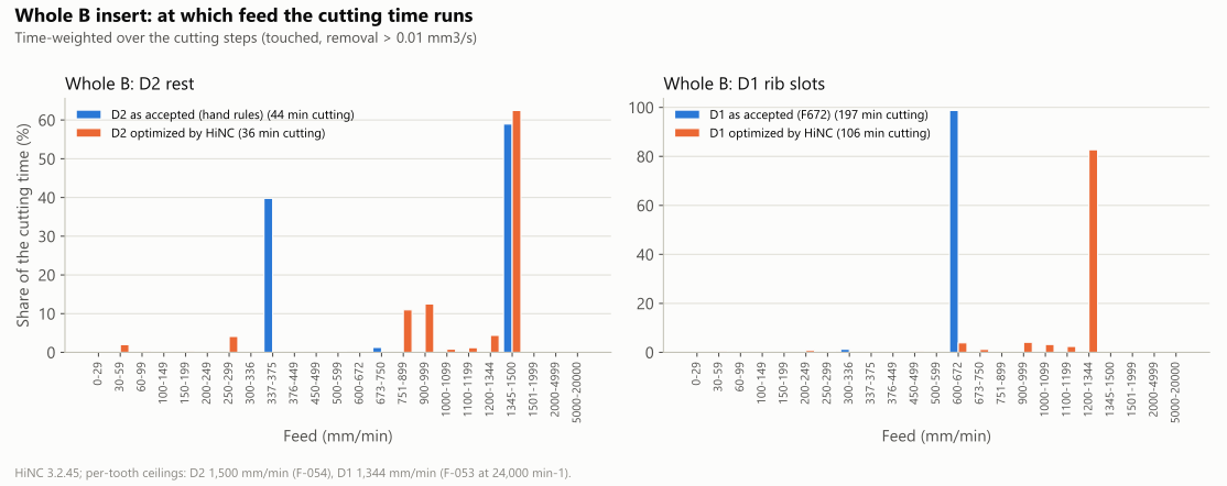
The whole insert: at which feed the cutting time runs. The Ø2 mm program's 375 mm/min corners give way mostly to feeds between 751 and 999; the Ø1 mm program moves from 672 to its 1,344 ceiling.
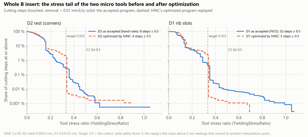
The whole insert: the share of cutting steps at or above each stress ratio. After optimization both tails end at the 0.333 target but for a few steps, which are readings that moved to another interpolation point (dilemma 3) or tips no feed brings down (dilemma 5).
The trimmed patch, the stress tail and the feeds of every variant:
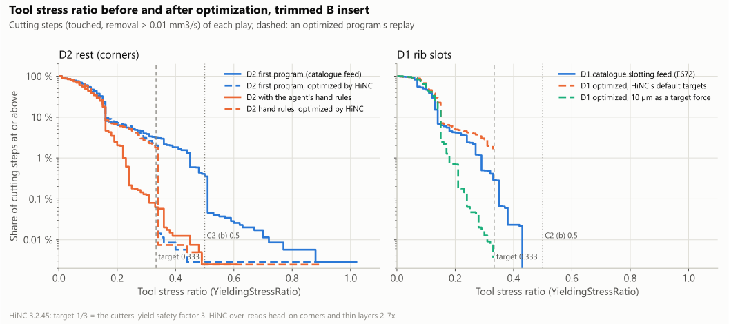
The trimmed patch: the share of cutting steps at or above each stress ratio; dashed, an optimized program's replay. HiNC can over-read the load where a small tool meets a corner head-on or runs its whole flute along a thin layer (the case page measured 2–7 times), so the optimizer slows those steps more than a real cut may need.
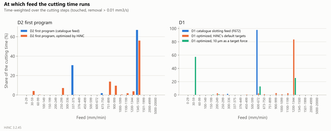
The trimmed patch: at which feed the cutting time runs. With the target force more than half of the Ø1 mm tool's cutting time runs at 30–59 mm/min.
Deflection. The optimizer has no built-in deflection criterion; on the Ø1 mm tool the deflection follows the feed:
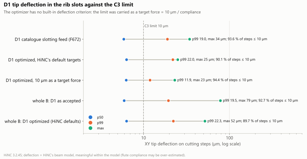
The Ø1 mm tool's XY tip deflection on its cutting steps against C3. Only the target force brings the 99th percentile near 10 µm, at 3.8 times the time.
What set the feed, from the optimizer's per-step log of each optimization play: for each cutting step of the source program, the criterion that allowed the lowest feed per tooth in the step's own solve, before the extended distances and the acceleration limit lower some feeds further:
| Play | Cutting steps | Catalogue ceiling | Tool stress | Target force | Target force, at the minimum feed | Relief angle | No load read | Spindle power or torque | Tool stress, at the minimum feed |
|---|---|---|---|---|---|---|---|---|---|
| V1-plain, D2 first program | 35,071 | 31,254 (89.1 %) | 1,834 (5.2 %) | — | — | 100 (0.3 %) | 1,878 (5.4 %) | 3 steps | 2 steps |
| V1-hand, D2 hand rules | 40,213 | 36,415 (90.6 %) | 1,848 (4.6 %) | — | — | 83 (0.2 %) | 1,862 (4.6 %) | 3 steps | 2 steps |
| V2a, D1 default targets | 65,041 | 62,691 (96.4 %) | 1,275 (2.0 %) | — | — | 176 (0.3 %) | 899 (1.4 %) | — | — |
| V2b, D1 target force | 65,041 | 59,522 (91.5 %) | 16 steps | 1,733 (2.7 %) | 3,594 (5.5 %) | 176 (0.3 %) | — | — | — |
| V3, D2 whole | 182,262 | 168,011 (92.2 %) | 6,935 (3.8 %) | — | — | 295 (0.2 %) | 7,007 (3.8 %) | 8 steps | 6 steps |
| V3, D1 whole | 365,932 | 342,706 (93.7 %) | 11,937 (3.3 %) | — | — | 236 (0.1 %) | 11,043 (3.0 %) | — | 10 steps |
The plunges in contact (the steps that move only Z) were set on the whole insert by the ceiling (787), the relief angle (236), the tool stress (27) and no load read (24) in the Ø1 mm program, and by the relief angle (287), the ceiling (79) and no load read (54) in the Ø2 mm program.
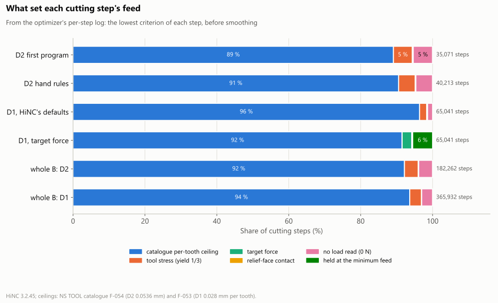
The limit that set each cutting step's feed, from the optimizer's per-step log.
HiNC's canvas: the Ø1 mm tool in a rib slot. Both programs on the trimmed patch played from their first line to the same source line, so the before and the after stop at the same point under one camera; the Ø1 mm end mill stands in the rib slot at Y 33 below its shrink-fit chuck. The optimized picture coloured by feed per tooth is at the top of the page.
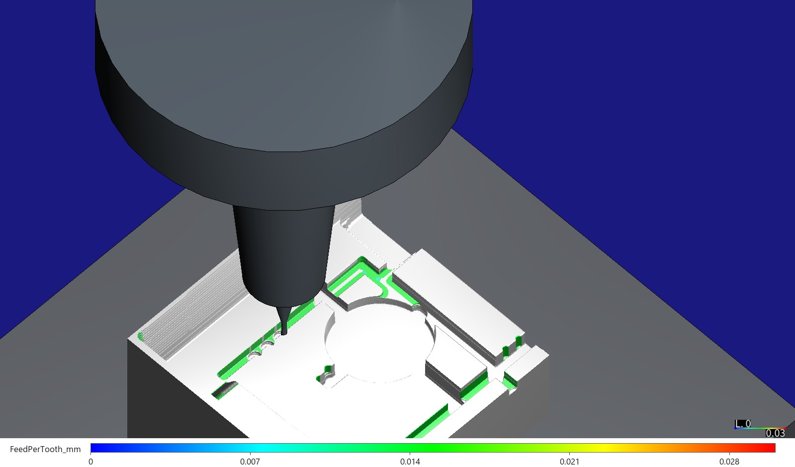
Before: the source program, the same pose and colouring as the picture at the top (feed per tooth, 0 to 0.03 mm). Every face the Ø1 mm tool cut is green, at the programmed 0.014 mm.
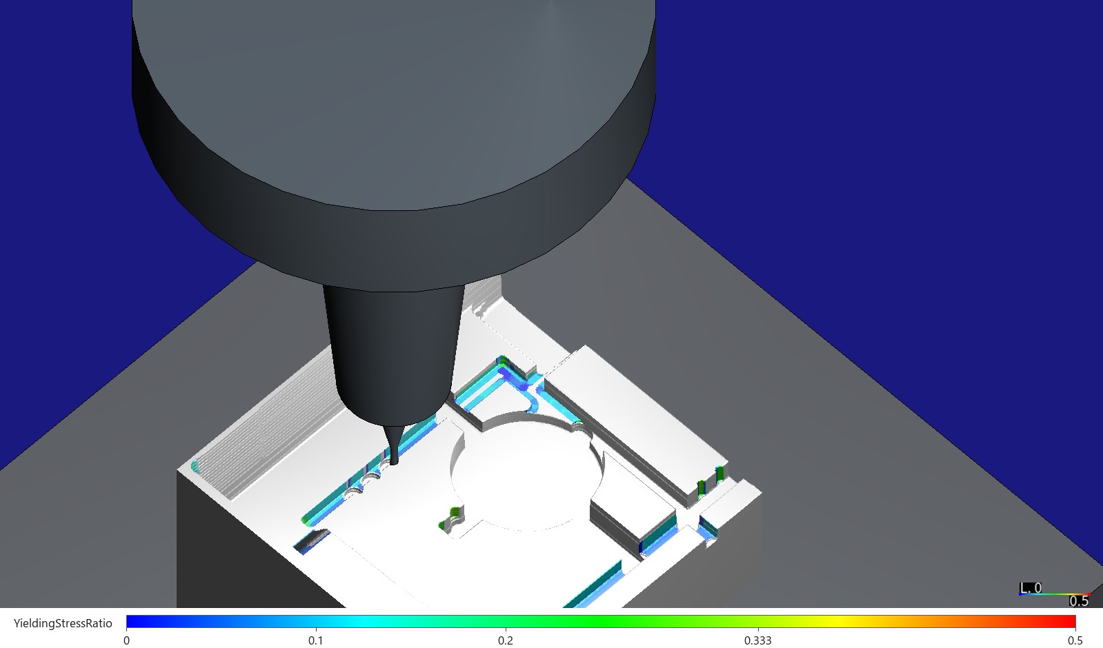
Before, coloured by stress ratio, 0 to 0.5: the slot faces blue to cyan.
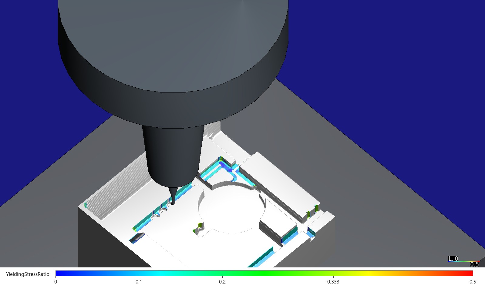
After, the same colouring: at up to twice the feed the slot faces stay blue to cyan. HiNC reads most of the Ø1 mm tool's steps far under its 0.333 target, at a median of 0.089 before and 0.098 after on the trimmed patch.
The optimized files. The optimizer gives a line a new feed, or splits it where the feed changes along it; the agent walked every written point back to its source line:
| Program | Lines, source → optimized | Feed lines kept / given a new F / split | Split lines by fragments (fragments: lines) | Feeds written | Points off their source line | Planned time, source → optimized |
|---|---|---|---|---|---|---|
| V1-plain, D2 first program (trimmed) | 98,285 → 98,958 | 16,590 / 76,540 / 557 | 2: 473, 3: 53, 4: 30, 5: 1 | 30–1,500 mm/min | 0 | 3,015.96 → 1,246.02 s |
| V1-hand, D2 hand rules (trimmed) | 109,155 → 109,664 | 12,293 / 91,828 / 436 | 2: 364, 3: 71, 4: 1 | 30–1,500 mm/min | 0 | 3,259.49 → 1,239.37 s |
| V2a, D1 (trimmed) | 37,539 → 38,521 | 3 / 30,709 / 883 | 2: 789, 3: 89, 4: 5 | 122–1,344 mm/min | 0 | 3,137.81 → 1,588.38 s |
| V2b, D1 (trimmed) | 37,539 → 40,638 | 8,003 / 21,412 / 2,180 | 2: 1,580, 3: 319, 4: 256, 5: 16, 6: 6, 7: 2, 8: 1 | 30–1,344 mm/min | 0 | 3,137.81 → 11,993.45 s |
| V3, D2 (whole) | 357,989 → 360,241 | 52,947 / 289,825 / 1,983 | 2: 1,746, 3: 225, 4: 8, 5: 1, 9: 1, 10: 1, 12: 1 | 30–1,500 mm/min | 0 | 10,835.51 → 5,009.18 s |
| V3, D1 (whole) | 235,960 → 243,178 | 6 / 193,959 / 6,561 | 2: 5,966, 3: 534, 4: 60, 5: 1 | 30–1,344 mm/min | 0 | 18,354.75 → 9,422.53 s |
The planned time is the agent's own: path over feed plus rapids at 24 m/min. The feeds written most often: on the whole insert's Ø2 mm program F1500 287,057 times, F960 12,138 and F1339 6,963; on its Ø1 mm program F1344 110,101 times, F933 22,775 and F1118 17,190. The program switches to F30 10 times in the whole insert's Ø1 mm program (the three teeth and seven slot ends of dilemma 5), 6 times in its Ø2 mm program, twice in each trimmed Ø2 mm program, 990 times in V2b and never in V2a.
The air-feed guard (O6), every optimized program walked over the agent's exact stock:
| Program | Feed moves (cutting on the exact stock) | Cutting above the ceiling × 1.02 | HiNC read air, stock under the tool's inner half | HiNC read air, stock at the rim only: share of the cutting length (median depth) | Contact path against the source's |
|---|---|---|---|---|---|
| V1-plain | 94,360 (20,969) | 0 | 0 | 15.6 % (0.043 mm) | +0.021 % |
| V1-hand | 105,066 (26,290) | 0 | 0 | 16.4 % (0.040 mm) | −0.010 % |
| V2a | 32,577 (21,325) | 0 | 0 | 8.3 % (0.0275 mm) | −0.0001 % |
| V2b | 34,694 (23,200) | 0 | 0 | 7.8 % (0.0275 mm) | −0.003 % |
| V3, D2 | 347,007 (107,263) | 0 | 0 | 11.3 % (0.042 mm) | −0.010 % |
| V3, D1 | 207,744 (135,729) | 0 | 0 | 10.7 % (0.0275 mm) | −0.001 % |
The shape (O3), each replay's exported stock against its baseline's, column by column on a 0.05 mm grid:
| Variant | Cut area | Columns within one mesh width | Outside one width: on walls / on flat ground | Largest difference below / above | Removed volume, baseline / replay |
|---|---|---|---|---|---|
| V1-plain (0.0625 mm) | 338.6 mm² | 99.986 % | 0.048 / 0 mm² | −1.44 / +1.19 mm | 558.98 / 558.98 mm³ |
| V1-hand (0.0625 mm) | 338.6 mm² | 99.984 % | 0.055 / 0 mm² | −1.43 / +0.81 mm | 558.96 / 558.97 mm³ |
| V2a (0.03125 mm) | 168.0 mm² | 100 % | 0 / 0 mm² | −0.00002 / +0.000005 mm | 242.64 / 242.64 mm³ |
| V2b (0.03125 mm) | 168.0 mm² | 99.999 % | 0.003 / 0 mm² | −0.081 / +0.006 mm | 242.64 / 242.64 mm³ |
| V3, D2 (0.0625 mm) | 1,825.6 mm² | 99.990 % | 0.175 / 0 mm² | −1.75 / +0.89 mm | 3,006.11 / 3,006.11 mm³ |
| V3, D1 (0.03125 mm) | 1,051.8 mm² | 99.984 % | 0.165 / 0 mm² | −1.78 / +0.91 mm | 1,402.32 / 1,402.31 mm³ |
Against the design, the whole insert's final stock after the Ø1 mm program, by the acceptance's own column-by-column check (0.05 mm, steep faces left out). The source chain and the optimized chain read the same numbers in every region:
| Region | Area | Height above the design, 1st / 50th / 99th percentile | Left more than 0.1 mm | Cut below by more than 0.0625 / 0.03125 mm | Deepest |
|---|---|---|---|---|---|
| Floors and gentle slopes | 11,785.5 mm² | +0.0002 / +0.0022 / +0.0054 mm | 0.02 mm² | 1.53 / 16.93 mm² | −0.182 mm |
| Parting face | 20,299.0 mm² | 0.0000 / 0.0000 / 0.0000 mm | 0 | 3.06 / 4.67 mm² | −0.077 mm |
| Rib slots | 2,614.4 mm² | −0.0337 / +0.0025 / +0.1618 mm | 39.92 mm² | 3.51 / 30.95 mm² | −0.187 mm |
| EDM regions (left for sinker EDM) | 1,860.0 mm² | +0.0023 / +0.0024 / +0.0703 mm | 16.11 mm² | 0.02 / 0.02 mm² | — |
| Patches, both chains | 189 patches, 56.04 mm² | 127 patches, 8.12 mm² |
What the runs cost, on the shared 32-thread server:
| Play | Steps | Server time | Peak memory (sampled) |
|---|---|---|---|
| Trimmed patch: roughing, semi-finishing, finishing (T0) | 25,010 / 26,008 / 178,799 | 50 / 40 / 220 s | 2.0 GB |
| Trial T1, D2: optimization / replay | 68,991 / 68,997 | 100 / 90 s | 2.8 GB |
| Trial T2, D1: optimization / replay | 27,705 / 27,705 | 40 / 40 s | in the 6.9 GB below |
| V1-hand: optimization / replay | 210,726 / 210,730 | 390 / 350 s | 6.9 GB |
| V1-plain: optimization / replay | 202,286 / 202,305 | 391 / 340 s | 9.9 GB, with V2a |
| V2a: optimization / replay | 184,340 / 184,418 | 661 / 461 s | 9.9 GB, with V1-plain |
| V2b: optimization / replay | 184,340 / 184,519 | 531 / 471 s | 9.8 / 7.8 GB |
| Whole insert: roughing, semi-finishing, finishing | 121,065 / 91,355 / 345,495 | 330 / 160 / 751 s | 4.6 / 4.5 / 5.8 GB |
| Whole insert, D2: optimization / replay | 1,200,719 / 1,200,806 | 1,812 / 1,632 s | 23.1 / 10.1 GB |
| Whole insert, D1: optimization / replay | 1,638,058 / 1,638,164 | 3,393 / 3,213 s | 35.3 / 15.7 GB |
The trimmed patch's plays took 70 min of server time in one evening and the whole insert's 3 h 8 min after them, each in its turn on the shared lock, held eight times: T0 20:11–20:22, T1 20:23–20:37, V1-hand with T2 20:42–21:31, V1-plain with V2a 21:33–22:05 and V2b 22:07–22:24; the whole insert's roughing, semi-finishing, finishing and Ø2 mm optimization 22:24–23:15, its Ø2 mm replay and Ø1 mm optimization 23:32–00:56, and its Ø1 mm replay 01:02–01:56. On the whole insert an optimization play needed about 2.3 times the memory of its replay (23.1 / 10.1 and 35.3 / 15.7 GB); V2b's on the trimmed patch, 1.3 times (9.8 / 7.8 GB).
For a machining engineer. On a mould insert whose micro tools run cautious hand rules and a halved slotting feed, HiNC's optimization took a third off the insert and kept all but a few of the micro tools' cutting steps within a third of yield. It did two different things. On the Ø2 mm program it mostly removed waiting: ramps and plunges through levels already cut went from the plunge feed to the air feed, and it found by itself the corners the hand rules had found, so the hand rules add nothing to its result. On the Ø1 mm program it doubled the feed wherever the slot cut was light, which is where the catalogue's slotting half is too cautious. What it does not do is hold the deflection: the Ø1 mm tool's typical bend rises with the feed, and no feed holds 10 µm in HiNC's model, so if 10 µm is a real requirement the path or the tool has to change, not the feed. The ceiling, the catalogue's feed per tooth, carries every step HiNC cannot read, and the three tooth tips need a different path, not a lower feed.
For a teacher or a student. One insert shows what a feed optimizer optimizes: the time it finds is mostly in the air the CAM left in its links, and in light cuts a catalogue allowance had slowed; the stress target holds where the model reads the load, and the feed at the ceiling holds where it does not. It shows why a deflection limit cannot be bought with feed when the force does not fall with the feed, why a replay can read a little above its target, and why the time saved has to be split before it is credited.
For someone weighing the approach. From two accepted micro programs to optimized programs for the whole insert took one evening and a night: five variants and two trials, 15 runs on a trimmed patch and 7 on the whole insert, about 4.3 hours of server time at up to 35 GB. The agent wrote its criteria, its plunge rule and its decision for the whole insert first, tested the optimizer against its own hand rules on the same path, reported the deflection criteria that failed and the target force that could not be met, and checked every written point and every air-feed move against its own model of the stock.
Honest limits
- The times are ideal-feed estimates, without the controller's acceleration and look-ahead: the ratios between versions are sound, the absolute times are not shop-floor times — see Machining Time Estimation. Much of the gain is feed through air that a different link in the CAM would also remove.
- Deflection is HiNC's tool-beam reading, not a measurement, and the removal geometry here does not include it: the case's projects play with HiNC's deflection transformation off, so the shape comparisons read the programmed path, and the larger bend of the optimized Ø1 mm program does not show in them.
- The optimizer has no built-in deflection criterion. C3 was carried by a target force; at 4.8 N, 5.5 % of the Ø1 mm tool's cutting steps stay above it at the 30 mm/min minimum, and the 10 µm is not reached.
- HiNC can over-read small tools' loads: where a small tool meets a corner head-on or runs its whole flute along a thin layer, the case page measured 2–7 times the exact cut; at the V-shaped tooth tips the force read falls only about with the 0.13th to 0.19th power of the feed per tooth. The optimizer slows those steps more than a real cut may need — the safe side, at a cost in time.
- A replay reads a few steps above the targets: the re-interpolated feed moves the sampling points, so a heavy reading can land on a step the optimization play had read light (4 and 5 steps at 0.5 or more on the whole insert).
- Steps that remove stock with no force read get the ceiling (1.4–5.4 % of the cutting steps); the ceiling, the catalogue's feed per tooth, is what bounds them.
- The grid is coarser than the Ø1 mm tool's levels: HiNC misses a thin cut at the tool's rim on 8–16 % of the cutting length, which the optimizer reads as air; the air feed was therefore held at the ceiling.
- A step record's path length on a line spans two steps at a fixed motion step; this page's path lengths come from the tool positions, and the optimizer's acceleration limit, which reads that field, allows up to twice the acceleration set on straight lines.
- Only the B insert's two micro programs were optimized: the roughing, the Ø6 mm passes and the A insert were not; each program ran as its own run.
- The machine and spindle are generic and the tools are catalogue tools in generic holders; the loads come from HiNC's shipped P20 data. Chip evacuation, chatter, tool wear and surface finish are not modelled, and nothing was measured on a machine.
What a reader can take to their own case
- Split the time saved into cutting, feed through air and rapids before crediting the optimizer; on CAM output with long links much of the gain is air.
- Give the optimizer the maker's catalogue feed per tooth as the ceiling. Every step the model cannot read runs at the ceiling, so the ceiling needs a source.
- Test hand rules against the optimizer on the same path: write the program once without them and let the optimizer find the corners; here both versions ended about 0.1 min (7 s) apart.
- Set the air feed for the cuts the grid cannot see: with levels thinner than the mesh, an air feed no higher than the ceiling keeps a missed cut within the catalogue's section; check the result against an exact model of the stock.
- Before carrying a deflection limit as a target force, count the steps at the minimum feed. If many sit there, the limit is not a feed problem.
- Read a replay's few over-target steps against the same place in the optimization play before calling them the optimizer's.
- Take path lengths from the tool positions when summing step records at a fixed motion step.
- Write the decision rules before the plays that decide them, and report the criteria that fail.
- Budget the memory: on the whole insert an optimization play here needed 2.3 times its replay's.
Source and licence
- Source. Telecom Infra Project, OpenCellular, https://github.com/Telecominfraproject/OpenCellular,
folder
hardware/connect-1/:cad/individual_parts/227-001264_SHORTY_ANTENNA_COVER.stepanddrawings/227-001264_SHORTY_ANTENNA_COVER.pdf(read 2026-09-30). Search terms if the link moves:OpenCellular 227-001264 SHORTY ANTENNA COVER. - Licence. The repository's README states that the documentation under
hardware/is licensed under Creative Commons Attribution 4.0 (CC BY 4.0);LICENSE-HARDWAREholds the legal text. The drawing frames still read “CONFIDENTIAL” and “DRAFT RELEASE 30/11/2016”, left over from before release; the repository publishes them under the licence above. - Attribution. “OpenCellular Connect-1 hardware, Telecom Infra Project, https://github.com/Telecominfraproject/OpenCellular, CC BY 4.0. Mould design and machining set-up by Tech Coordinate's agent.” Provided by the licensor without warranty.
- Changed. The mould, the stock, the tools, every program and their optimization here are the agent's; the mould's case page tells what the agent made of the part. This page reproduces nothing of the drawing or the part model: the pictures are HiNC simulations of the agent's insert, and the charts are drawn from HiNC's per-step results, the optimizer's per-step log and the agent's own model of the stock.
- Backup. The company site keeps a copy of the original files.
See Also
- OpenCellular Antenna Cover: Two Injection-Mould Inserts — how the inserts, the tools and the programs optimized here were made and accepted
- NC Optimization — what the optimizer holds, the extended distances and why a replay can read above a target
- Workflow: NC Optimization — the settings, the tool limits and the per-step log
- Optimization Results — measured before-and-after comparisons on other parts
- Machining Time Estimation — why the ratio of two simulated times is the part to trust
- Relief Face Avoidance — the relief-angle limit that set some plunges
- Showcase — the other cases and how a case page reads