Heatsink porthole die: an extrusion die rebuilt from a paper's drawings (3-axis)
- Original source
- T.-T. Truong (Hung Yen University of Technology and Education; National Kaohsiung University of Science and Technology), Q.-C. Hsu (NKUST, Department of Mechanical Engineering), V.-C. Tong (Korea Institute of Machinery and Materials), J.-J. Sheu (NKUST, Department of Mold and Die Engineering), A Design Approach of Porthole Die for Flow Balance in Extrusion of Complex Solid Aluminum Heatsink Profile with Large Variable Wall Thickness, Metals 2020, 10, 553 (doi:10.3390/met10050553).
- Search keywords
porthole die heatsink large variable wall thickness Truong Hsu Sheu,met10050553- Licence
- CC BY 4.0. The paper's figures are not reproduced; the pictures are HiNC renderings of the agent's model, and drawings and charts made by the agent's own scripts.
- Attribution
- Die and profile geometry after T.-T. Truong, Q.-C. Hsu, V.-C. Tong, J.-J. Sheu, Metals 2020, 10, 553, doi:10.3390/met10050553, CC BY 4.0. Die model and machining set-up by Tech Coordinate's agent.
- About the case
- A two-plate porthole die, Ø180 mm and 90 mm tall, that extrudes a twelve-fin aluminium heatsink with walls from 1.51 to 23.13 mm; the paper's authors designed it by simulation, had it made and extruded the profile on a 930-ton press.
The story
The paper publishes drawings and a handful of dimensions, not a model. An AI agent read the proposed die off the figures — its porthole areas came out within 2.3 % of the paper's — and decided what a die shop mills and what it leaves to wire EDM: the portholes, the welding chamber, the bridge's chamfers, the pocket and the relief behind the bearing are milled; the die orifice and its bearing are wire-cut and left out. It wrote four set-ups and eight Fanuc programs with its own CAM, wrote its pass criteria down before the first play, and drove HiNC through its web API.
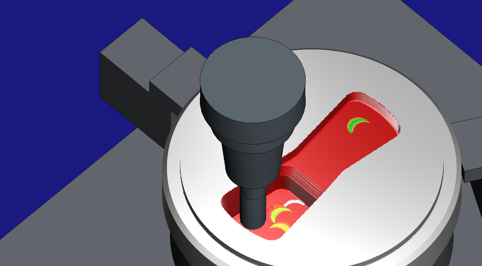
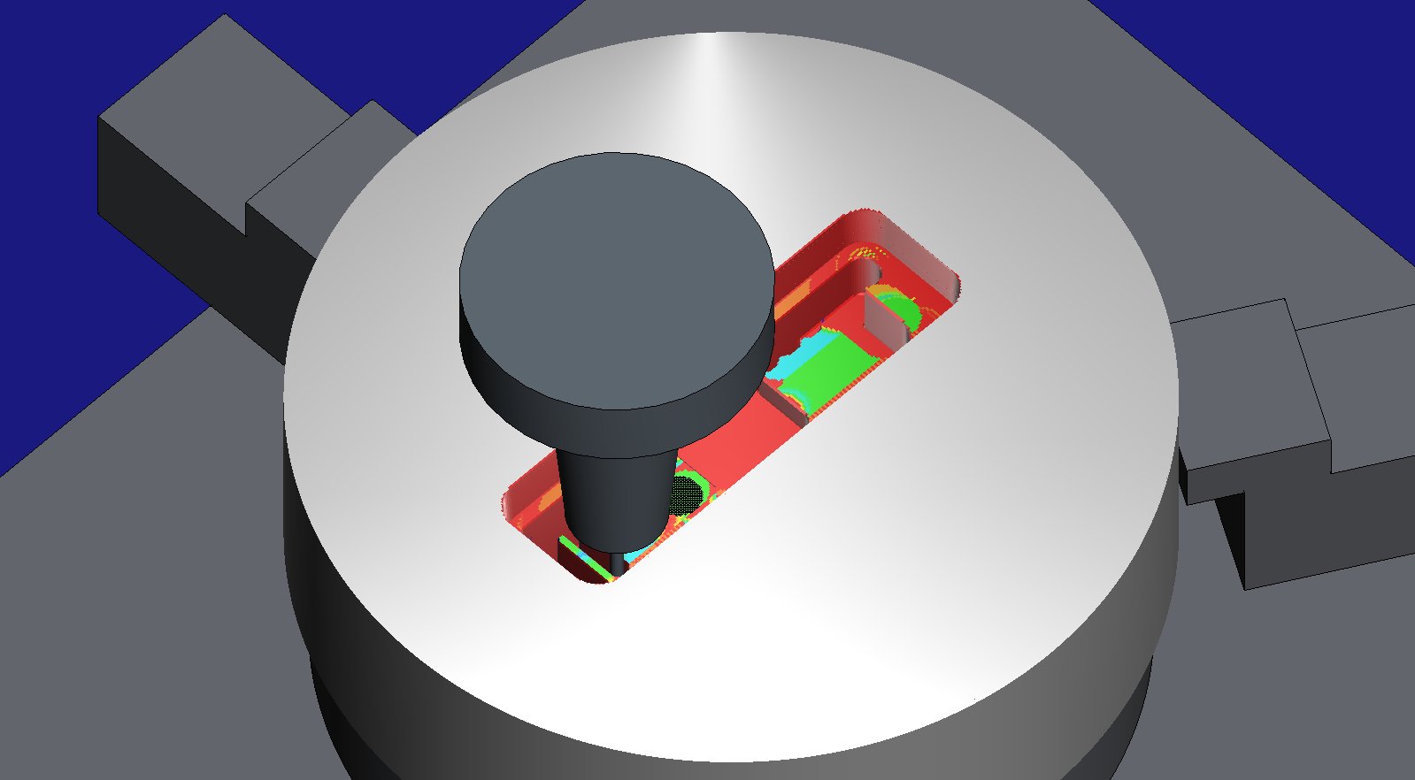
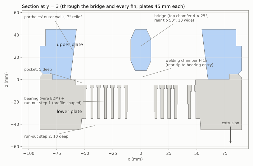
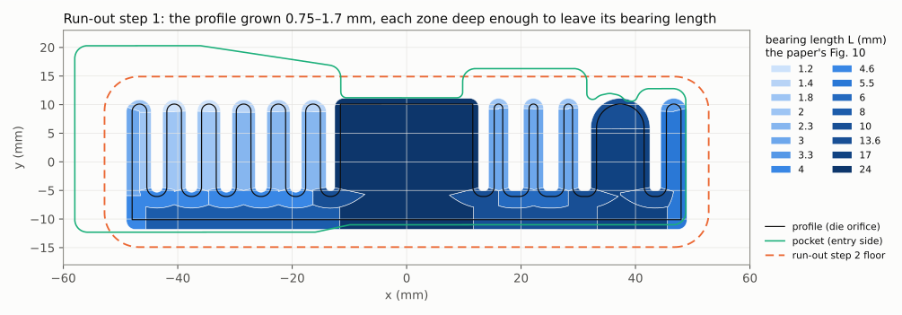
Pictures rendered by HiNC from the die model Tech Coordinate's agent built after the paper's figures; not the authors' CAD. The section and the charts are drawn by the agent's own scripts from that model and from the plays.
Four of its ten dilemmas
Rapid moves through stock
HiNC's first play reported four rapid moves that cut steel, up to 27 mm deep. The crossings between cutting levels ran the tool's edge along the roughing wall with no clearance. The agent made every rapid keep 1 mm off the walls and added its own height-field replay of each program before every later play; the rerun reported none.
One side cannot reach everything
The portholes open 7° towards the lower plate, the bridge's top chamfer the other way, so one of them is an undercut from either face. The upper plate is machined from its joint face and turned over only for the two chamfers.
Bearing lengths made from the back
The bearing is wire-cut through the whole plate, yet its length runs from 1.2 to 24 mm along the profile. The relief behind it is milled from the exit side in 16 depth zones, each leaving its segment's length; at the fin tips the zone is narrower than a 3 mm cutter, which the criteria named beforehand as work for EDM.
A grid coarser than the step-down
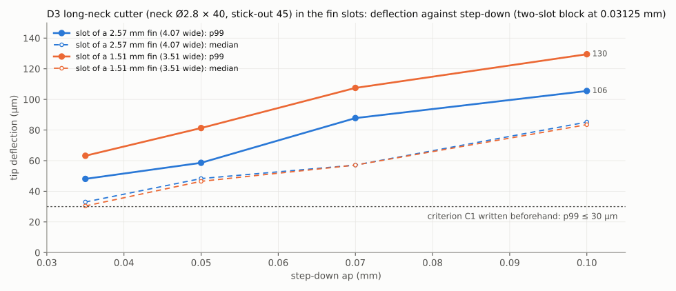
At 0.5 mm HiNC read the 3 mm cutter's 0.1 mm step-down as whole layers and its bending as 0.44 mm. The agent cut the case down to two fin slots and played them at 0.03125 mm with four step-downs in one program.
The other six, among them two dies in one paper, a source note that took the extrusion ratio for the ram speed, a build setting that slowed the play to two or three steps a second, and a 14 mm plunge the agent's own check caught before HiNC played it, are in the full record.
The result
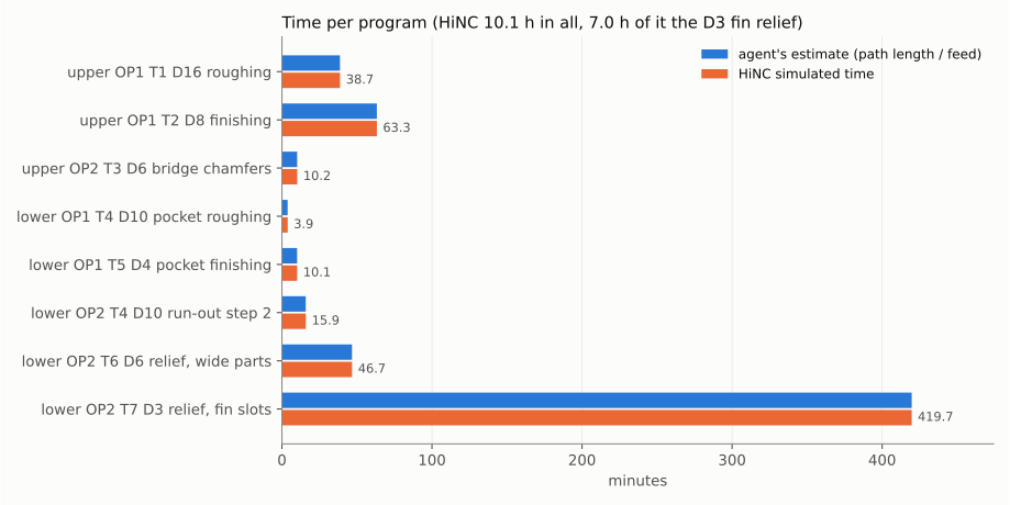
The four set-ups played every line at 0.25 mm with no alarm and no collision, and the milled faces of the upper plate and the pocket came within ±0.15 mm of the model on 99.9–100 % of the points. The porthole roughing used 0.194 of the spindle's 11 kW continuous power and 0.14 of the tool's yield stress, and took 38.73 min against the agent's estimate of 38.68. Both plates take 10.1 h of machining, 7.0 h of it the 3 mm cutter in the eleven fin slots; there the cutter bends 106–130 µm at a 0.1 mm step-down (48–63 µm at 0.035 mm) against the 30 µm the agent set beforehand, and about 2 % of the relief lies in bearing zones narrower than the cutter. By the rule written before the first play (over 4 h, recommend EDM), the fin relief goes to EDM, and the milling program stays as the evaluated alternative. Three criteria were not met — the cutter's bending, the relief's share within ±0.15 mm, and the deepest point past the model (−0.32 mm on edges no tool touched, −0.78 mm on the relief) — and the full record says so. The four acceptance plays took 73 minutes on a shared 32-thread server. Everything is simulated; no die was cut.
| Key number | What it is |
|---|---|
| 10.1 h | simulated machining of both plates: upper 1.9 h, lower 8.3 h, of which the 3 mm cutter in the fin slots 7.0 h; tool changes, turn-overs and wire EDM not included |
| 1927 / 1663 mm² | the model's porthole entrance areas against the paper's 1960 / 1702 mm² (−1.7 %, −2.3 %): the check on the reading of the drawings |
| 4 → 0 | rapid moves through stock HiNC reported: four on the first coarse play, up to 27 mm deep, none in the acceptance; no collision |
| 0.194 | the porthole roughing's highest spindle power against the 11 kW continuous rating; the limit written beforehand was 0.8 |
| 100 % / 99.9 % / 100 % | share of the milled faces within ±0.15 mm of the model: the upper plate from its joint face, from its billet face, and the pocket |
| 98.1 % | share of the relief outside the profile within ±0.15 mm; the rest lies in bearing zones narrower than the 3 mm cutter and deeper than their neighbours |
| 106–130 µm | the 3 mm long-neck cutter's tip deflection, 99th percentile, at a 0.1 mm step-down on the two-slot block; the limit written beforehand was 30 µm |
| 4.9 h + 2.1 h | the 3 mm cutter's 7.0 h in the fin slots: cutting, and feed through air where the tool leaves a slot and comes down again |
| 73 min | the four acceptance plays at 0.25 mm together, on a shared 32-thread server |
NC optimization of this case →
What it brought
- For a machining engineer: before any steel is cut, HiNC shows that the porthole roughing sits far inside the tools' strength and the power of the generic BT40 spindle it was set up with (11 kW continuous), gives the time of every program, and shows where a long-neck 3 mm cutter stops paying: seven hours, a tenth of a millimetre of bending, and bearing zones it cannot reach. That is the evidence behind the usual choice to sink the fin relief by EDM and mill the rest.
- For a teacher or a student: how a porthole die is split between milling and wire EDM, why a die is machined from both faces, how bearing lengths are made from the back, and why a simulation grid must be finer than the step-down it judges.
- For someone deciding whether to use an agent with HiNC: from a paper's drawings to an accepted simulation of both plates, with its own model, CAM and checks; the pass criteria were fixed before the first run, and no second agent rebuilt the case.
Read the full case record: heatsink porthole die
The source and its backup
| Case | Original files | Backup |
|---|---|---|
| Heatsink porthole die | the article (Metals 2020, 10, 553) | Showcase-Heatsink-PortholeDie.zip |
The zip holds the case's SOURCE.md and, under Setup/, the
agent's scripts that build the die from the figures and write the programs, the numbers files with every
value marked read, measured, derived or chosen, the pass criteria and the accepted results. The
publisher's 12.8 MB article stays at the source, under CC BY 4.0; the scripts rebuild the meshes.