Heatsink porthole die: HiNC's feed optimization takes 13 % off both plates, and no feed keeps the 3 mm fin-relief cutter within 30 µm (3-axis)
- Original source
- T.-T. Truong (Hung Yen University of Technology and Education; National Kaohsiung University of Science and Technology), Q.-C. Hsu (NKUST, Department of Mechanical Engineering), V.-C. Tong (Korea Institute of Machinery and Materials), J.-J. Sheu (NKUST, Department of Mold and Die Engineering), A Design Approach of Porthole Die for Flow Balance in Extrusion of Complex Solid Aluminum Heatsink Profile with Large Variable Wall Thickness, Metals 2020, 10, 553 (doi:10.3390/met10050553).
- Search keywords
porthole die heatsink large variable wall thickness Truong Hsu Sheu,met10050553- Licence
- CC BY 4.0. The paper's figures are not reproduced; the pictures are HiNC renderings of the agent's model, and the charts are drawn by the agent's own scripts from the plays.
- Attribution
- Die and profile geometry after T.-T. Truong, Q.-C. Hsu, V.-C. Tong, J.-J. Sheu, Metals 2020, 10, 553, doi:10.3390/met10050553, CC BY 4.0. Die model and machining set-up by Tech Coordinate's agent.
- About the case
- The accepted programs of the heatsink porthole die: a two-plate aluminium extrusion die rebuilt from a paper's drawings, four set-ups and eight Fanuc programs from the agent's own CAM, one programmed feed each, 608.6 minutes of machining. Here HiNC's feed optimization rewrites their feeds.
The story
The die's programs had passed their acceptance with room to spare: each ran at one feed the agent had picked as a safe value for pre-hardened die steel, the porthole roughing asked for a seventh of the spindle's short-term rating, and the 3 mm long-neck cutter in the fin slots spent two of its seven hours feeding through air. An AI agent handed the programs to HiNC's feed optimization and wrote down first what it wanted to know: how much margin the roughing had left, how much of the feed through air could come back, and what holding the finishing and the long-neck tools would cost. It gave every tool a feed-per-tooth ceiling with a stated source, held the finishing passes at their programmed chip with a force target derived from each tool's own compliance, ran five trials before the whole die, and replayed every optimized program on the same machine and grid against criteria fixed before the first run.
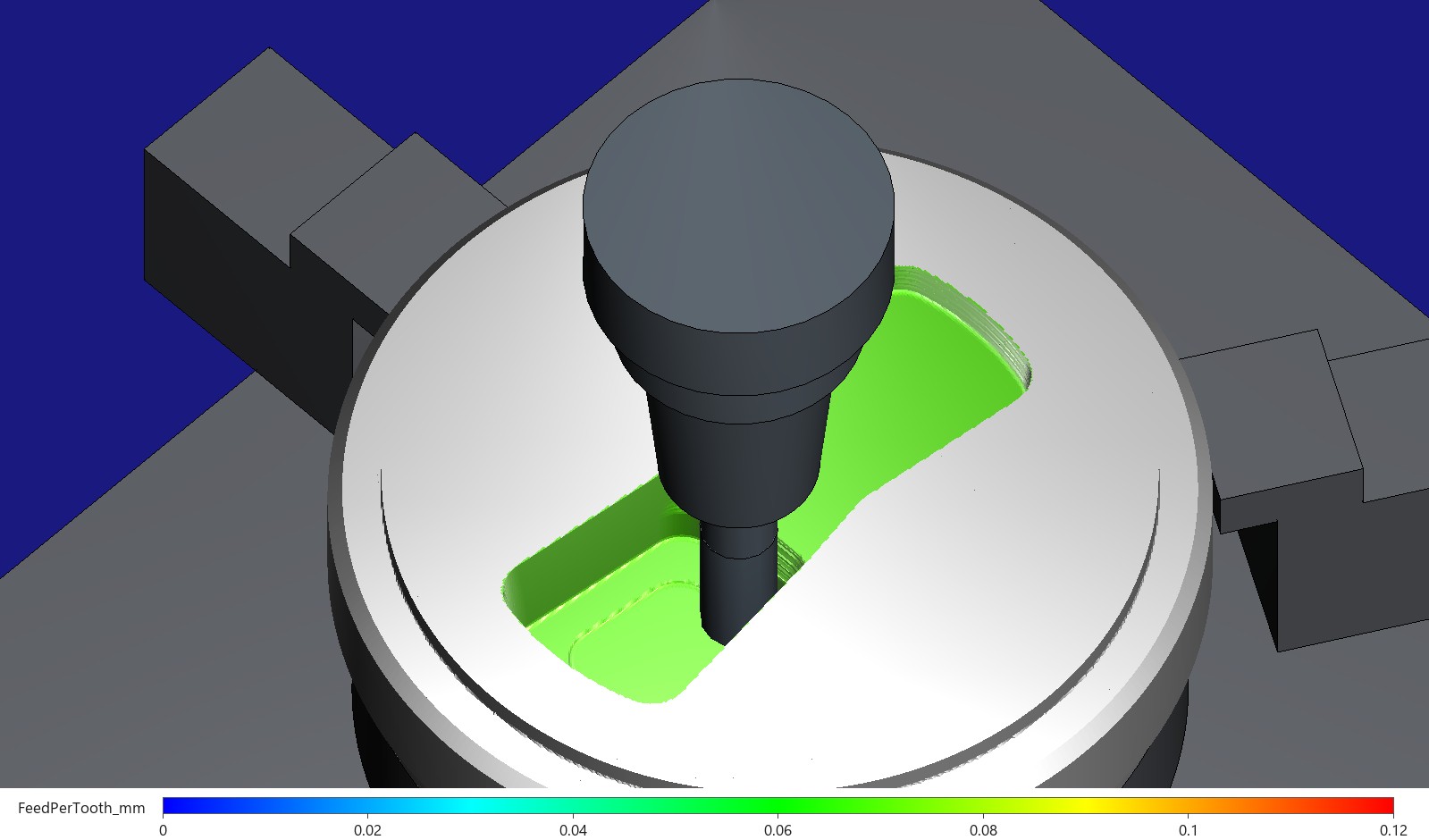
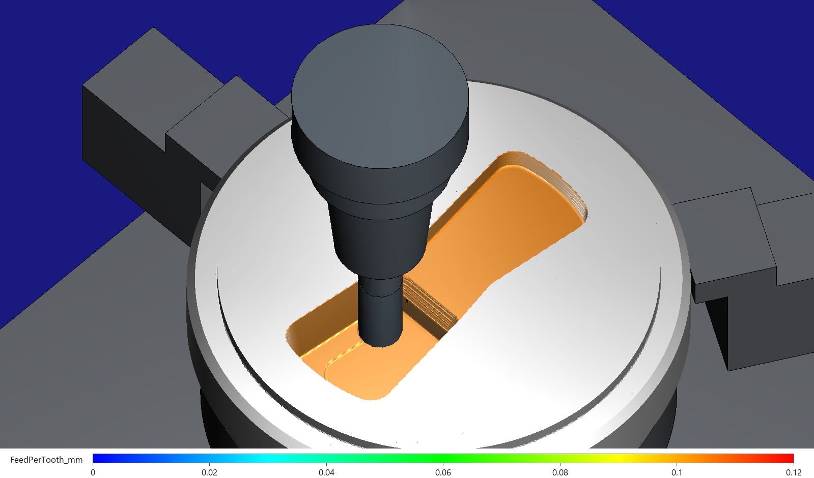
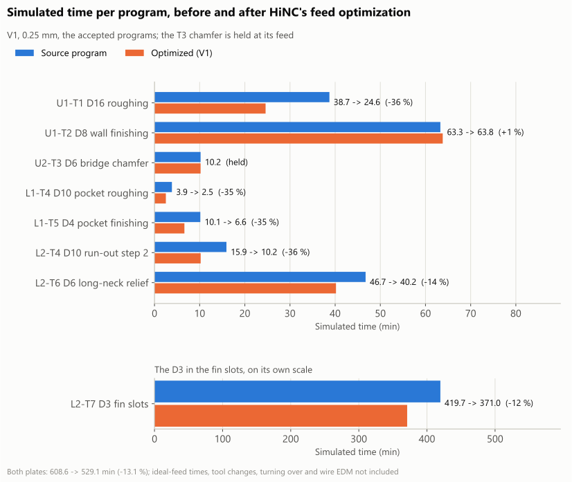
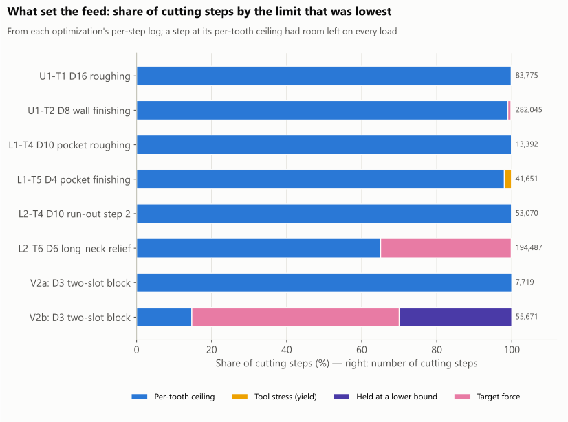
Pictures rendered by HiNC from the die model Tech Coordinate's agent built after the paper's figures; not the authors' CAD. The charts are drawn from HiNC's per-step results by the agent's own scripts; the times are HiNC's ideal-feed estimates, so compare the ratios rather than the absolute times.
| Key number | What it is |
|---|---|
| 608.6 → 529.1 min | both plates' simulated machining, eight programs (−13.1 %); tool changes, turn-overs and wire EDM not included |
| 188.9 → 158.2 min | the seven programs other than the 3 mm fin relief (−16.3 %) |
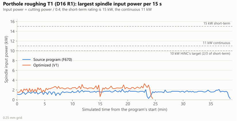
| 38.7 → 24.6 min | the porthole roughing, nearly every cutting step at the feed-per-tooth ceiling; its spindle power at most 0.219 of the short-term rating, against a target of 0.667 |
| 122 → 78 µm | the wall finishing's largest tool deflection, its chip held as programmed and a force target trimming the peaks, for 0.8 % more time |
| 125.7 → 77.0 min | the 3 mm cutter's feed through air in the fin slots; its 291.6 minutes of cutting unchanged |
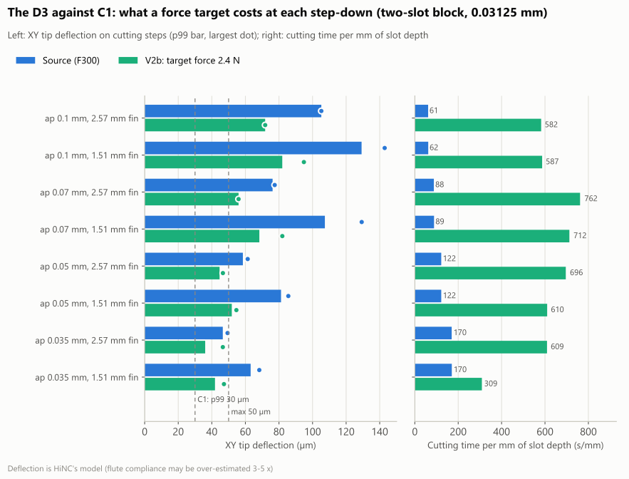
| 72–82 µm | the 3 mm cutter at a 0.1 mm step-down with a force target for its 30 µm limit: the feed down at its 30 mm/min minimum and the limit still not met; about 47 h for the whole fin relief |
| 0 | cutting moves at the air feed in the final programs, by the agent's own z-map; 38 and 105 found and removed on the way |
| 100 / 100 / 96.09 % | of the milled faces within ±0.15 mm of the model on the upper plate's porthole side, the pocket and the relief side, as before the optimization; no point moved more than 0.16 mm |
| 3.5 h | for the study's 22 plays on a shared 32-thread server; up to 20 GB for an optimization play, 3 to 5 GB for a replay |
Four of its twelve dilemmas
The air feed meets what the finishing leaves
A first trial gave every stretch with no contact 20,000 mm/min. Many of them follow a contour the finishing pass has just cut, and a finishing tool leaves as much stock as it bends away; HiNC's replay read a stress ratio of 1.56 there. So each tool's air feed is set so that a residue as thick as its own deflection gives no thicker chip than the program's: 740 to 9,250 mm/min.
A web thinner than the grid
On the porthole roughing's last layer the plate's bottom is a 0.2 mm web, thinner than a 0.25 mm cell. The stock model cannot see it, so the first optimized program ran 38 moves of that layer at the air feed, and HiNC's own replay could not see them either. The agent's exact z-map did; the break-through layer is now held at its programmed feed.
A held block takes the feed of the line before it
HiNC copies held lines into the optimized file word for word. The held layer had no feed word of its own, so it ran at the air feed the optimizer wrote on the line before it: 105 moves, read by HiNC's replay at 4,029 N. With the programmed feed restated on the held block's first line, the final program has none.
No feed brings the 3 mm cutter within its limit
With a force target set for its 30 µm limit, the optimizer drove the 3 mm cutter's feed down to its 30 mm/min minimum in every step-down band. A tenth of the feed only halved the force, and the bending stayed at 72–82 µm. Scaled to all eleven slots that is about 47 hours, still over the limit: the case for EDM, in hours.
The other eight, among them chamfer layers thinner than the grid, the agent's own check raising two false alarms, statistics skewed by the slow-downs, and two capture locks waiting for each other, are in the full record.
The result
Every optimized program replayed to its end with no collision, no rapid move through stock and no new warning, and the milled faces kept their shape. Both plates came down from 608.6 to 529.1 simulated minutes. The roughing took about a third less time, nearly every cutting step at the feed-per-tooth ceiling the agent set, 1.5 times the programmed chip, while the spindle stayed under a quarter of its short-term rating: the ceiling, not the spindle, set the pace. The finishing kept its programmed chip, and a force target from each tool's compliance cut the wall finishing's largest deflection from 122 to 78 µm. The 3 mm cutter in the fin slots won back 48.8 minutes of feed through air, but on its own no feed meets its 30 µm limit: HiNC's default targets would take a third off its time and bend it further, and a force target for the limit costs about 47 hours and still misses. Three criteria were not met as written, the long-neck tool's force target among them, and the full record says so. Everything is simulated; no die was cut.
What it brought
- For a machining engineer: on programs written with one safe feed each, HiNC's optimization takes a third off the roughing within the spindle's rating, keeps the finishing at its programmed chip while trimming its worst deflection, and gives back feed through air where the stock model sees air. It also prices the fin relief: no feed keeps the 3 mm cutter within 30 µm, and the slowest feed that tries costs about 47 hours, so the fin relief goes to EDM.
- For a teacher or a student: what HiNC's feed optimizer holds (spindle power, torque, tool stress, a target force) and what it does not (a tool's bending, unless a force target stands in for it); why it speeds up only to its ceilings; why it cannot tell air from a layer thinner than its grid; and when a target is out of reach of any feed.
- For someone deciding whether to use an agent with HiNC: from accepted programs to optimized programs for both plates, with the criteria fixed first, every target derived from the case's own numbers, and the agent's own z-map catching three ways the air feed could have cut steel; the 22 plays took 3.5 hours of a shared server.
Read the full case record: the porthole die's NC optimization
How the die, its programs and their acceptance were made: Heatsink porthole die. The source and its backup are listed there.