Connecting-rod forging die: impressions designed from a forging drawing and a photo (3-axis)
- Original source
- A. Dziubińska (Warsaw University of Technology), The New Technology of Die Forging of Automotive Connecting Rods from EN AB-71100 Aluminium Alloy Cast Preforms, Materials 2023, 16(7), 2856 (doi:10.3390/ma16072856).
- Search keywords
Dziubińska 2023 connecting rod EN AB-71100 die forging,ma16072856- Licence
- CC BY 4.0. The right-hand picture below puts the article's photo of the real dies (Fig. 11a), with its credit, beside the agent's die, and a picture in the second row draws the agent's rebuilt outlines over the article's forging drawing (Fig. 3); the deflection chart is the agent's, drawn from HiNC's step data, and so are the die render, the section and the tool paths; everything else in the pictures is rendered by HiNC.
- Attribution
- Forging drawing and die photograph: A. Dziubińska, Materials 2023, 16, 2856, doi:10.3390/ma16072856, CC BY 4.0. Die design and machining set-up by Tech Coordinate's agent.
- About the case
- A closed-die forging of an automotive connecting rod, forged from an EN AB-71100 aluminium cast preform; the article's drawing gives it 140.86 mm long with 82.5 mm between the centres of its ends. The author tested the process on a crank press and a screw press in industrial conditions. Aluminium connecting rods are a niche: most car connecting rods are steel forgings. The article gives the forging's drawing and a photo of the dies, but no die drawing, no die steel and no machining.
The story
The article publishes the forging's dimensioned drawing, its volume and a photo of the dies used in the tests. An AI agent rebuilt the forging from the drawing, designed the lower die around it and sized the die on the photo. The forging is symmetric about its parting plane and its axis, so the upper impression is the same shape, cut by the same programs; only the lower half was played. For a generic three-axis machining centre the agent chose three solid-carbide cutters, a D10 R1 end mill, a D6 ball and an R1.5 long-neck ball, each 20 mm out of an HSK-A63 shrink chuck, and wrote their Fanuc programs with the height-field CAM script an agent wrote for an earlier case, adapted here. It checked every move on its own z-map before any play, wrote its pass criteria down before the first one, and drove HiNC through its web API: a trimmed window of the die at 1 mm first, then the whole die at 1 mm, the trimmed window at 0.125 mm to size the run, and the whole die at 0.125 mm.
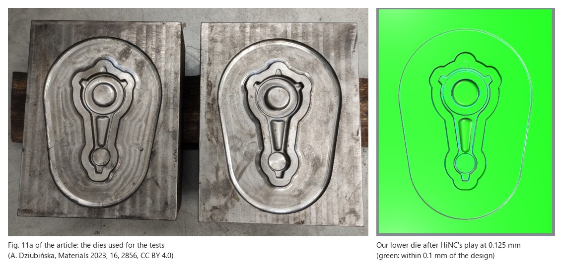
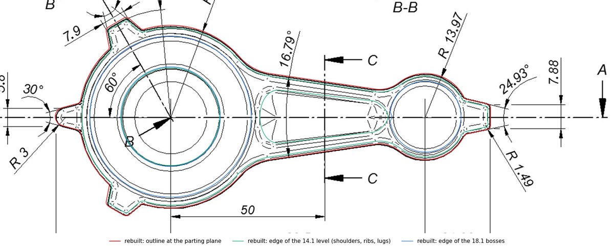
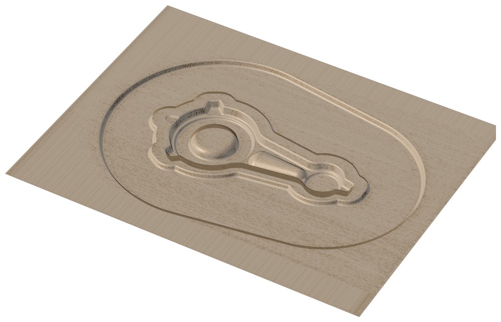

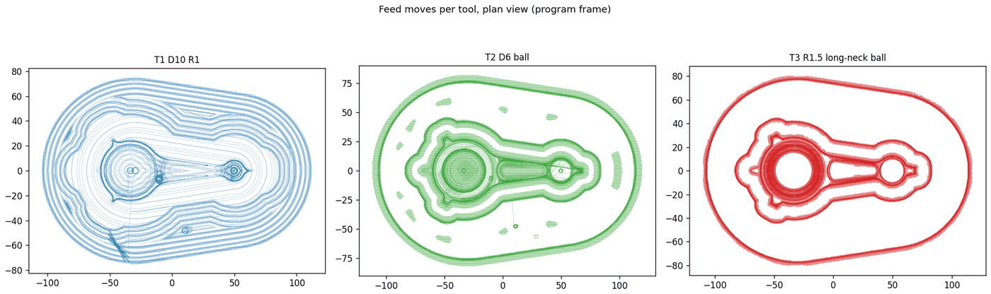
The photo of the dies is the article's Fig. 11a, and the drawing under the rebuilt outlines its Fig. 3 (A. Dziubińska, Materials 2023, 16, 2856, CC BY 4.0). The die render, the section and the tool paths are drawn by the agent's own scripts; everything else is rendered by HiNC from the die Tech Coordinate's agent designed; the author published no die drawing.
Four of its seven dilemmas
A forging read off one drawing
The first rebuild made both ends 18.1 mm thick all over and guessed the shank pocket; its volume came out 2.1 % above the article's 58,299.9 mm³. Three independent reviewer agents checked it against the drawing and the die photo, and another agent tried to refute each finding. Five findings held: three on the forging (18.1 mm only on the bosses with a 14.1 mm shoulder round them, true arcs at the necks, the pocket's shape) and two on the die (the land and gutter, the block). The second version comes within 0.4 % of the article's volume, and its neck outline within 0.05 mm of the drawing at seven stations. Its lugs stay up to 0.45 mm wider than the drawn line: the agent followed their dimensions, which the drawn line does not meet.
A die known only from a photo
The agent put the parting plane at mid-height and grew the impression 0.8 % for shrinkage, derived from the article's preform at 480 °C and dies at 250 °C. From the photo it took three sizes. The flash land is 9.5 mm wide (8–11 mm on the photo). The egg-shaped gutter is 226 × 159 mm. The block is 265 × 205 mm (about 263 × 205 on the photo). The 1.2 mm flash, the 4 mm gutter depth and the FDAC pre-hardened steel are its own choices; the article names no die steel.
An R1.5 ball in an R1.5 corner
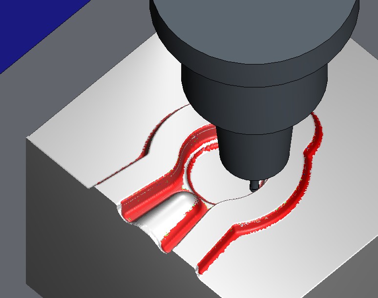
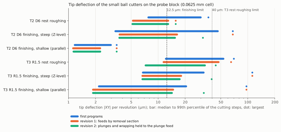
The whole die was played at 0.125 mm, coarser than this ball's 0.04 mm finishing allowance, so the agent read its loads on a 12 × 11 × 12 mm probe block at 0.0625 mm. On that block every peak of this ball sat on one line: the concave R1.5 corner where a rib groove's floor meets the core that forms the shank pocket. A ball of the corner's own radius cuts there with its whole quarter arc. HiNC read the contact 1.5 mm high and 1.2 mm wide, forces up to 208 N and the tip bent up to 112 µm, against the 12.5 µm set beforehand. The criteria said beforehand what a failure calls for: change the program, replay, report both numbers. The agent revised the feeds of the two ball programs twice. The first revision slowed each segment whose removal cross-section on its z-map exceeds a limit, down to a quarter of the programmed feed. Replayed in HiNC on the probe block, it cut the 99th percentile of the steep-wall finishing deflection by about half (D6 46.3 to 16.2 µm, this ball 32.1 to 18.0 µm), but this ball's largest step stayed at 112 µm. HiNC's step data showed why. The largest steps were descents into the groove, one of them straight down into the corner at the cutting feed. And a ball in a corner of its own radius takes a thin layer with its whole arc, which a cross-section rule cannot see. The second revision holds such descents, and segments where more than 60° of the ball's arc cuts at once, to the tool's plunge feed (300 mm/min for this ball, 500 for the D6).
One rapid that grazed the stock
HiNC's acceptance play reported one rapid through stock: a rapid descent in the roughing program removed 0.00025 mm³, about an eighth of one of HiNC's 0.125 mm cells. The agent walked that program again line by line on its own 0.1 mm z-map: the move keeps 1.0 mm from the stock, and every rapid in the program at least 0.99 mm. It reads the message as a contact at the scale of the grid. The criterion allowed no such message, so it stays failed, as written.
The other three are in the full record, among them the agent's own mistakes caught before the acceptance: a straight feed that gouged the flash land 3 mm deep on the whole die, where the trimmed window could not show it; a Ø2.8 neck on the Ø3 ball that a freshly cut wall touched; 1,300 m of rapids by the R1.5 ball, back and forth across the die, because the gutter ring was taken as one rest region.
The result
On the whole die at 0.125 mm, HiNC played every line of the three programs (70,567, 190,004 and 400,570 lines; 3,722,141 steps) with no collision. Its time per program came within 0.04 % of the agent's own arithmetic: one half of the die takes 5.71 h (64.9 min of roughing, 278.0 min of finishing) and the pair 11.43 h. The agent measured the stock HiNC exported against the design, on a 0.1 mm grid inside the gutter, along the surface normal: 99 % of the milled face stands at most 0.040 mm proud, and the deepest point is 0.034 mm inside. The only spots more than one of HiNC's 0.125 mm cells proud, 0.87 mm² in all, are where the agent's z-map also leaves stock. With the R1.5 ball held 8 mm out instead of 20 (trimmed window, 1 mm), HiNC reported its holder hitting the workpiece on the move the z-map had predicted. Of the criteria written before the first play, A1, B1–B3, C4, D1 and E1 passed. Three failed: A2 by the letter, on one message; C1 and C2 outright, on the two balls. The message: a rapid descent removed 0.00025 mm³ of stock. The agent's z-map gives that move 1.0 mm of clearance, so the agent reads it as a contact at the scale of HiNC's 0.125 mm grid. On the balls, the stress reached 0.83 (D6) and 1.04 (R1.5) of the tool's yield stress against 0.5 allowed, and the tip deflection 68 µm (D6) and 127 µm (R1.5) against 12.5 µm (the whole die replayed for its NC optimization). C3, D2 and E2 are reported, not judged. C3's predictions missed in places: T1's power peaked at 1.40 kW against the 0.2–0.6 kW predicted, and T3's finishing force reached 58 N at the 99th percentile on the probe against under 30 N. The acceptance play took 77.7 min and 16.5 GB of memory on a shared server.
Criterion C2 named its own remedy: change the program, replay, report both numbers. The agent revised the feeds of the two balls twice, as the R1.5 card above tells. It judged the revised programs' loads on the probe block only, so the verdicts above, judged on the first programs, stand. After the second revision HiNC read on that block, at 0.0625 mm: the R1.5 ball's largest finishing deflection down from 112 µm to 40 µm, and its largest force from 208 N to 74 N; the D6's largest finishing deflection down from 68 µm to 32 µm; the largest stress ratio 0.35 for the R1.5 ball and 0.38 for the D6 (0.91 and 0.84 before), inside C1's 0.5 on that block. The finishing deflection is still over the 12.5 µm limit. In steep finishing its 99th percentile is 17 µm for the R1.5 ball and 15 µm for the D6, and 10 % of the R1.5 ball's steep-finishing steps that cut are over the limit, along the wall of the same groove. The R1.5 ball's rest roughing still peaks at 44 µm against 40 µm. For the largest steps what is left is the entry, not the feed: they are now a straight plunge into the corner, already at the plunge feed, and the first move of a level pass after its descent. The revisions cost time. By the agent's arithmetic one half of the die now takes 439.1 min (7.32 h), 28 % more than the first programs. HiNC's times of the revised T2 and T3, played on the whole die for this case's NC optimization, are within 0.03 % of the agent's arithmetic, and with T1's from the acceptance they give the same 7.32 h. Everything is simulated; no die was cut.
| Key number | What it is |
|---|---|
| 58.52 cm³ | the rebuilt forging's volume with its fillets; the article gives 58.30 cm³ (+0.4 %), and the first rebuild was 2.1 % over |
| within 0.04 % | HiNC's time for each program against the agent's own feed-and-rapid arithmetic |
| 5.71 h / 11.43 h | one half of the die / the pair, the first programs as HiNC timed them |
| 7.32 h / 14.64 h | the same after the second feed revision, 28 % more |
| +0.040 mm | the cut die against the design along the normal, 99th percentile; the deepest point 0.034 mm inside |
| 0 | holder and neck collisions at the 20 mm stick-out; held 8 mm out, the R1.5 ball's holder hit the workpiece on the move the agent's z-map predicted |
| 150–208 N, 81–112 µm | force and tip deflection of the R1.5 ball finishing the R1.5 corners, on the probe block at 0.0625 mm; the limit is 12.5 µm |
| 112 → 112 → 40 µm | the R1.5 ball's largest tip deflection in steep finishing on the probe block: first programs → revision 1 → revision 2 |
| 32.1 → 18.0 → 17.4 µm | the same operation's 99th percentile |
| 16.5 GB, 77.7 min | peak memory and run time of the whole-die acceptance play at 0.125 mm (3,722,141 steps) |
NC optimization of this case →
What it brought
- For a machining engineer: before any steel is cut, HiNC points at where this die's smallest ball is overloaded: in the R1.5 corners of the rib grooves, where a concave corner of its own radius makes it cut with its whole quarter arc; the D6 ball bends up to 68 µm on the steep walls in HiNC too. It gives each program's time, within 0.04 % of the agent's own feed-and-rapid arithmetic, and it confirms that at a 20 mm stick-out the holders clear the 9.12 mm deep impression (by 11.48 mm or more on the agent's z-map, with no collision in HiNC). Its step data then named the moves behind the largest loads: the entries into that corner. Not tried here: entering that corner from the side instead of plunging into it; a semi-finishing pass along the groove, or a slower feed for the whole operation; or a smaller ball for it (R1, for example, one more tool).
- For a teacher or a student: how a closed-die forging die is laid out round the forging: the parting plane, a shrink allowance worked out from two temperatures, the flash land and the gutter. Why a ball the size of the corner it finishes is loaded hardest there. And why a trimmed window, cheap to replay, can miss a mistake that only the whole die shows.
- For someone deciding whether to use an agent with HiNC: from one drawing and one photo to an acceptance play of the whole die; the forging model, the die, the programs and the checks are agents' work. Reviewer agents checked the forging against the drawing, the pass criteria were fixed before the first play, and the three that failed are reported as failed. No second agent rebuilt the case.
Read the full case record: connecting-rod forging die
The source and its backup
| Case | Original files | Backup |
|---|---|---|
| Connecting-rod forging die | the article (Materials 2023, 16, 2856) | Showcase-Conrod-ForgingDie.zip |
The zip holds the case's SOURCE.md; the numbers file, with every
value marked as read from the drawing, measured on the drawing or the photo, taken from the article's
text, derived or chosen, and the pass criteria written before the first play; the whole-die and trimmed
programs with their check logs, as revision 2, the version the case keeps, with both feed revisions
(the acceptance played the first programs); the acceptance verdict and the measurement of the cut die;
and the probe block's tip deflection for the first programs and both revisions. The publisher's 8.0 MB article and the design meshes stay out: the article
at the source, under CC BY 4.0, the meshes because of their size.