Connecting-Rod Forging Die: A Forging Rebuilt from One Drawing, a Die Sized on a Photograph, and an R1.5 Ball in an R1.5 Corner
A paper from Warsaw University of Technology (Dziubińska, Materials 2023) describes a new way to die-forge automotive connecting rods from cast aluminium preforms, tested in industrial conditions. It publishes the forging's dimensioned drawing and a photograph of the real dies, but no die drawing, no die steel and nothing about machining.
An AI agent rebuilt the forging from the drawing. Three reviewer agents overturned its first version; the second came within 0.4 % of the paper's forging volume. The agent designed the lower die around it, sized the flash land, the gutter and the block on the photograph, wrote three programs with a height-field CAM an earlier case's agent wrote, adapted for this die, and played the whole die in HiNC 3.2.43 through the web API. At a 0.125 mm cell the cut die matched the design inside the gutter to +0.040 mm at the 99th percentile, and nowhere in the gutter lay more than 0.034 mm inside it (nothing more than one 0.125 mm cell inside); HiNC's time matched the agent's arithmetic to 0.04 %: 5.7 h for one half, 11.4 h for the pair, before the feed revisions.
Three criteria failed at the acceptance: A2, C1 and C2. Both balls bent past the 12.5 µm limit, the R1.5 up to 112.4 µm on a finer probe block and the D6 up to 68.1 µm (the probe block replayed on HiNC 3.2.45 for the NC-optimization study), and their stress ratios passed the 0.5 allowed (1.04 and 0.83 at the acceptance). The R1.5 ball finishes R1.5 concave corners with its whole quarter arc. A2 failed by the letter: one rapid move grazed 0.00025 mm³ of stock.
As the criteria prescribed, the agent revised the feeds and replayed the probe block, twice. The first revision slowed the feed where the removed section is large. It lowered the 99th percentile, by about half in the Z-level finishing (T3 32.1 → 18.0 µm, T2 46.3 → 16.2 µm), but left the largest step of every finishing operation unchanged (T3 Z-level 112.4 µm, T3 parallel 96.7 µm, T2 Z-level 68.1 µm); T3's rest roughing fell only from 70.0 to 65.1 µm. HiNC's step data showed what those steps were: descents into the groove at the cutting feed, and the ball wrapping a corner of its own radius. The second revision held them to the plunge feed. On the probe block the largest deflection of the R1.5 ball's Z-level finishing then fell from 112.4 µm to 39.6 µm (its rest roughing's from 70.0 to 43.9 µm), and the ball's largest stress ratio from 0.91 to 0.35, inside the 0.5. One half takes 28 % longer by the agent's arithmetic, which HiNC's times of the revised programs match to within 0.03 %. The finishing still bends past 12.5 µm, so C2 stays failed. The largest steps left are entries into the corner. Holding the descents to the plunge feed was not enough; what is left to change is the entry. The verdicts are the first programs': the revisions change only feeds, and their loads were judged on the probe block only.
Aluminium connecting rods are a niche: most car connecting rods are steel forgings. Everything here is simulated; no die was cut on a real machine, and the die is the agent's design, not the authors'.
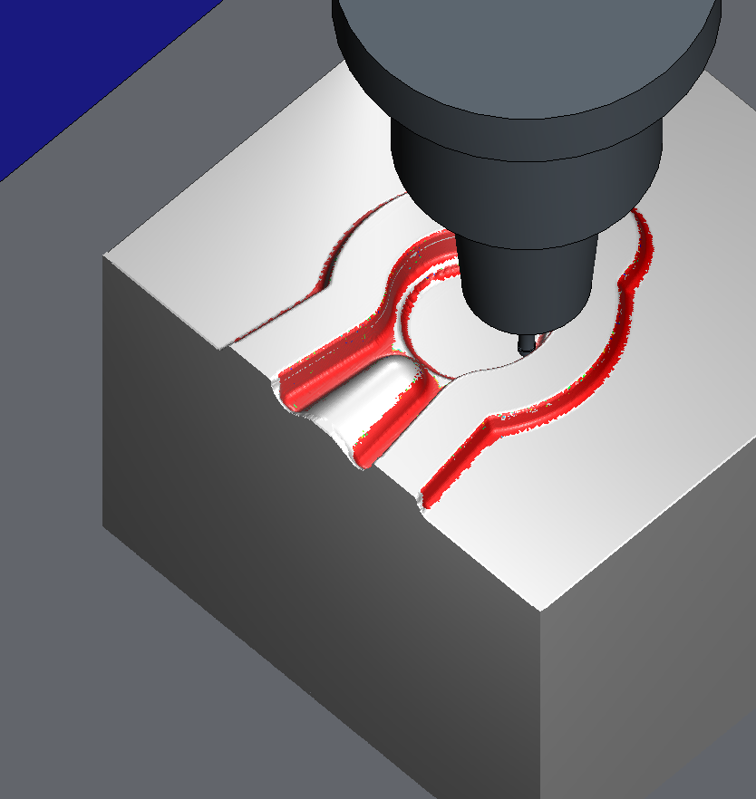
The trimmed case on HiNC's canvas, paused in T3's Z-level finishing at NC line 80,198 (0.125 mm cell, HiNC 3.2.43). The R1.5 ball on its Ø2.6 × 12 mm neck and Ø6 shank sits 20 mm out of an HSK-A63 shrink-fit chuck. Red marks the surfaces T3 has cut so far: the forging's R1.5 edges.
The case
The article gives:
- The process: EN AB-71100 cast preforms at 480 °C, dies heated to 250 °C, a crank press (ZDAS LU 400/1000) and a screw press (F1736A), “verified in the course of tests conducted in industrial conditions”.
- The forging drawing (Fig. 3): length 140.86 mm, centre distance 82.5 mm, 18.1 mm thick, 5 mm webs, a 3 mm tab at the big end, 7° draft, R1–R6 fillets, and the angles and widths of the lugs, the shank and the tabs.
- The forging's volume: 58,299.9 mm³ (0.166 kg).
- A photograph captioned “Dies used for tests with finishing impressions” (Fig. 11a). That it shows the upper and lower halves with their flash gutters is the agent's reading.
What it leaves out: a die drawing, the die steel, the sizes of the flash land, the gutter and the block, and anything about machining. The drawing does not dimension the blends between the shank and the ends, or the small end's boss.
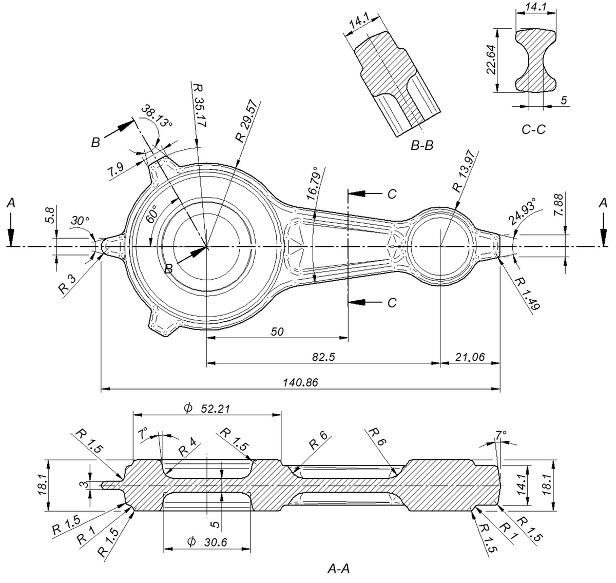
Fig. 3 of the article, “Selected dimensions of the connecting rod forging”: the one drawing the forging was rebuilt from. Drawing: A. Dziubińska, Materials 2023, 16, 2856, CC BY 4.0, scaled down.
What the agent built
Each value is marked read (stated by the article), measured (read off a figure at its scale), derived (worked out from read values) or chosen (the agent's decision).
The forging
| Item | Value | |
|---|---|---|
| Plan | big end R29.57; two lugs at 60° reaching R35.17, 7.9 wide, 38.13° taper; left tab R3 at 30°; shank sides at 16.79°, 22.64 wide at section C-C, 50 mm from the big-end centre; small end R13.97; right tab 7.88 wide, 24.93°, R1.49 | read (Fig. 3) |
| Neck blends | R16 towards the big end, R10 towards the small end | measured |
| Heights | 18.1 only on the bosses (big end Ø52.21, small end about R11.5); a 14.1 shoulder round them running into the lugs, the shank ribs and the right tab; left tab 3; webs 5; 7° draft on every wall | read; the small boss measured |
| Pockets | big end Ø30.6 at the wall's foot, R4. Shank: its section one arc from the axis to a rim 6.86 mm off it at C-C, the rims converging at 6.7°, both ends R6 with a 30° wall, the floor from 35 to 64.3 mm from the big-end centre | read and measured on the sections |
| Fillets | R1.5 on the outer edges, R1 at the inner corners and the flash line | from the drawing's R1–R6 |
| Volume | 58.52 cm³ with the fillets (58.94 cm³ sharp), against the article's 58.30 cm³: +0.4 % | derived |
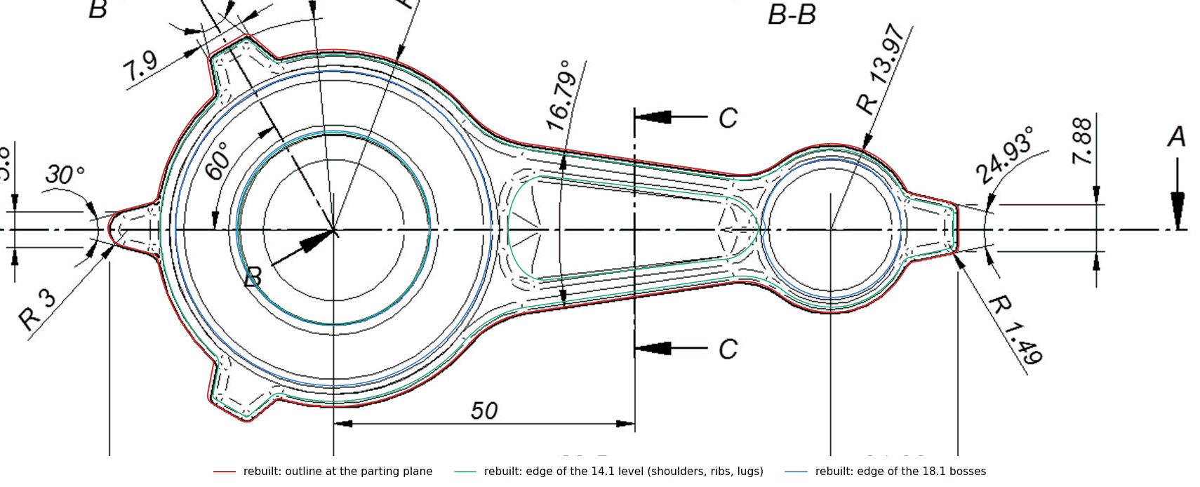
The rebuilt outlines over Fig. 3, scaled by the two centres (82.5 mm = 710 px); both ends fall within 0.15 mm of the drawing. Drawing: A. Dziubińska, Materials 2023, 16, 2856, CC BY 4.0, cropped, with the outlines drawn over it.

The upper half of the rebuilt forging; the lower half is its mirror image.
The die
| Item | Value | |
|---|---|---|
| Parting plane | at mid-height. The forging is symmetric about it, so both impressions are one shape and one program cuts both halves | derived |
| Shrinkage | impression grown 0.8 %: aluminium 23.6e-6/K × 460 K less steel 12.5e-6/K × 230 K, from the article's 480 °C preform and 250 °C dies | derived |
| Flash | 1.2 mm thick: the land 0.6 mm below each die face | chosen |
| Flash land | 9.5 mm wide | measured on the photo (8–11 mm) |
| Gutter | one convex, egg-shaped recess 226 × 159 mm with no waist: the hull of an R79.5 circle 3.5 mm from the big-end centre towards the small end and an R67.5 circle 0.5 mm from the small-end centre towards the big end | measured on the photo |
| Gutter depth, walls | 4 mm, 20° | chosen (the photo does not show them) |
| Block | 265 × 205 × 80 mm | measured on the photo (about 263 × 205); height chosen |
| Material | FDAC, a pre-hardened SKD61-type steel, about 40 HRC, milled at that hardness | chosen (the article names no die steel) |
| To machine | deepest point 9.12 mm; 111.7 cm³ to remove | derived |
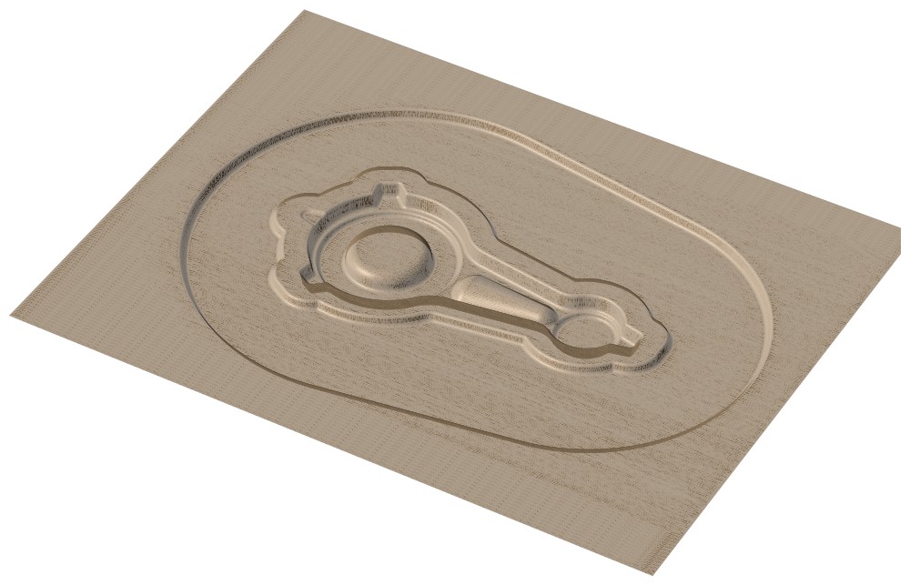
The lower die as the agent designed it, rendered from its height field: the impression, the flash land and the gutter in the 265 × 205 mm block. The upper die is the same shape.
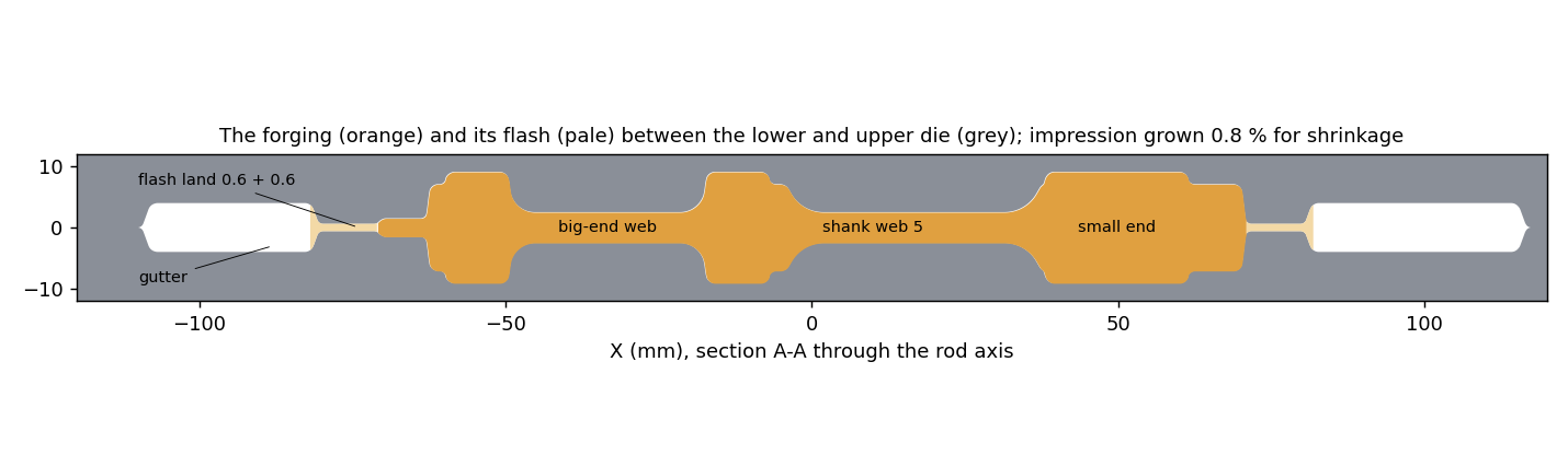
Section A-A of the agent's die with the forging in place; the impression is grown 0.8 % for shrinkage.
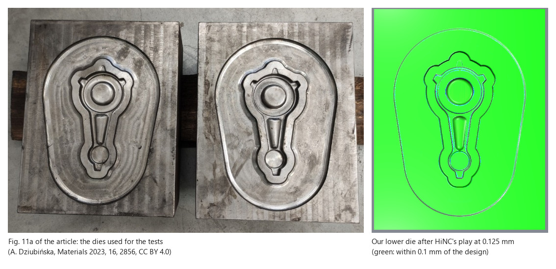
Left: Fig. 11a of the article (A. Dziubińska, Materials 2023, 16, 2856, CC BY 4.0), cropped. Right: HiNC's geometry difference of the agent's lower die after the acceptance play (0.125 mm, HiNC 3.2.43).
Machine, tools and programs
Every value in the two tables below is chosen, except the planned times, which are the agent's arithmetic (feed length over F, rapids at 24 m/min), and the 110 mm tool length (gauge 90 + stick-out 20).
| Item | Value |
|---|---|
| Machine | HiNC's three-axis skeleton Empty-wXYOZSt: travels 800 / 500 / 500 mm, rapids 24 m/min; a 300 × 220 × 20 mm sub-plate |
| Spindle | a generic 24,000 rpm spindle, 7.5 kW continuous, 10 kW short-term |
| Controller, program zero | Fanuc; the centre of the block's top face |
| Holders, stick-out | HSK-A63 shrink-fit chucks, 4.5° taper, 90 mm gauge, nose R12 (T1) or R10.5 (T2, T3); 20 mm stick-out, the shortest that reaches the bottom; tool length 110 mm |
| Resolution | 1 mm first, 0.125 mm for the acceptance, 0.0625 mm on a probe block for the loads |
| Mission | after each program Record Meshed Geometry writes the stock, and the next program reads it back (A Mission That Resumes) |
| Tool (generic solid carbide) | What it cuts | Speed, feed | Planned time: first programs → revision 1 → revision 2 |
|---|---|---|---|
| T1 D10 R1, 4 flutes, 15 mm flute | Z-level roughing (0.6 down, 4 across, 0.25 left), then the flat floors to size (land, gutter floor, shoulders, webs) | 3,800 rpm, F1050 | 64.8 min (not revised) |
| T2 D6 ball, 2 flutes, neck Ø5.7 to 18 mm | Z-level rest roughing (0.3 down, 1.2 across, 0.12 left); finishing Z-level on steep walls, along X elsewhere (0.25 step) | 10,000 rpm, F1200 | 101.1 → 117.9 → 122.0 min |
| T3 R1.5 ball, 2 flutes, 2.4 mm flute, neck Ø2.6 to 12 mm | where the D6 cannot reach (the R1.5 edges, the rib and shoulder corners): rest roughing in levels along X (0.15 down, 0.4 across, 0.04 left), then finishing (0.15 step) | 12,000 rpm, F900; finishing F1200 | 176.8 → 220.1 → 252.3 min |
For the first programs the planned times come to 342.8 min, 5.71 h for one half, 11.43 h for the pair, in programs of 70,567, 190,004 and 400,570 lines. The acceptance played these. Two feed revisions followed, described in the dilemmas below. They change only the feeds of T2 and T3, not the paths. The case keeps revision 2 as its programs: one half 439.1 min (7.32 h), 28 % more than the first programs. In it, a large removed section slows the feed, and steep descents into the stock and segments where the ball wraps a corner are held to the tool table's plunge feed: F500 for T2, F300 for T3.
The CAM works on height fields; an earlier product case's agent wrote it for a die-cast mould, and this agent added T3's rest roughing in levels and the checks. Before HiNC played anything, the agent checked every program on its own z-map: no move below the design's drop-cutter surface along the normal (worst −0.01 mm); the holder at least 11.48 mm from the stock, T2's neck 4.06 mm, T3's neck 0.514 mm; every rapid within 0.3 mm of the stock turned into a feed; after T3 at most 0.219 mm of rest, 126.8 mm² of it over 0.05 mm.
A trimmed case runs the same programs computed on a window x 15..110, y −50..50 mm: the small end, the right tab, the end of the shank pocket, the land and part of the gutter; 91 min of machining for the first programs by the agent's arithmetic (111.7 min in revision 2).

Feed moves per tool, in the program frame (mm), as played in the acceptance.
How the agent managed the work
- Pass criteria first. Written and committed before the first play: A, the run (every line
runs, every program cuts, no message beyond one
Sys-Init--FileLinesper program); B, the holder (the agent's z-map, no collision in HiNC, and a negative control that must raise one); C, the small cutters (stress ratio, tip deflection, spindle ratios, predicted loads); D, the shape; E, the time. The 12.5 µm deflection limit is a quarter of the ±0.05 mm taken as the impression's tolerance. C2 named its own remedy: change the program, replay a cut-down case, report both. - Small before large. The trimmed case at 1 mm, the negative control, the whole die at 1 mm, the trimmed case at 0.125 mm, then the whole die once at 0.125 mm. It would fall back to 0.25 mm if the trimmed runs predicted more than 8 h or 24 GB; they predicted 18–20 GB (central), at most 31 GB. The agent went ahead on the central estimate, and the play peaked at 16.5 GB (Memory Planning).
- An independent review. Three reviewer agents checked the first forging against the drawing, its sections and the die photo; each finding went to another agent told to refute it. Fifteen agents in all.
- Watching the plays. Every three minutes a read-only look at alarms, the share of steps in contact and the loads (Replay Acceptance §2).
- A shared server. A private copy of the deployed HiNC 3.2.43 on a server shared with other agents; heavy plays queue on one lock.
- Where a person stepped in. The set-up follows the Showcase rules: public data only, every cutter in a holder at a shop's stick-out.
The dilemmas
Measured numbers are from HiNC 3.2.43, except the loads read on the probe block (tip deflections, forces, stress ratios, contacts and shares of steps), which are from the probe block's replay on HiNC 3.2.45 for the NC-optimization study, and, where marked, the whole die's deflections and revision 2's times from the same study.
One drawing, and a first forging overturned
- Situation. The forging exists only as Fig. 3, and some shapes are drawn but not dimensioned. The first version made both ends 18.1 mm thick all over, used 8 mm rounds at the necks and guessed the shank pocket: 2.1 % over the article's volume.
- Risk. Programs, times and loads for a part that is not the paper's.
- Noticed. The agent had the first version reviewed against the drawing.
- Resolution. Five findings held: 18.1 mm only on the bosses, with a 14.1 mm shoulder; true R16 and R10 arcs at the necks; the pocket's shape and ends; the land and gutter; the block. The forging and the die were rebuilt with them.
- Evidence. The second version against values measured on the drawing:
| Checked | On the drawing | Difference |
|---|---|---|
| Outline half-width at the necks, 7 stations | 8.86–17.65 mm | ≤ 0.05 mm |
| Shank pocket at C-C, 5 points | 3.18–6.51 mm | ≤ 0.22 mm |
| Pocket end on section A-A, 6 points | 2.55–6.9 mm | ≤ 0.28 mm |
| Boss edges, 3 places | 26.1, 71.5, 93.65 mm | ≤ 0.35 mm |
| Lug width, 4 stations | 3.91–6.14 mm | +0.11 to +0.45 mm |
| Volume with fillets | 58.30 cm³ (article) | 58.52 cm³, +0.4 % |
The lugs are wider on purpose: the agent followed their dimensions (7.9 mm, 38.13°), which the drawn outline does not meet.
No die drawing: the die sized on the photograph
- Situation. The article shows the real dies only in a photograph.
- Risk. A land, gutter and block unlike a real forging die.
- Noticed. Reading the article: it gives no die dimension.
- Resolution. Land width, gutter outline and block measured on the photo; flash thickness, gutter depth and wall angle chosen; shrinkage derived. Each is marked in the die table.
- Evidence. The photo and HiNC's result side by side, above: one convex gutter with no waist, a land and a block of the same proportions.
Loads read on a grid coarser than the finishing allowance
- Situation. The acceptance cell, 0.125 mm, is coarser than the 0.04 mm T3 leaves for finishing.
- Risk. Judging the smallest cutter on loads the grid distorts.
- Noticed. In the plan of the plays: the 0.125 mm cell is coarser than the 0.04 mm T3 leaves for finishing, so its forces and deflections were to be read on a finer probe as well.
- Resolution. A probe: the whole-die programs over a 12 × 11 × 12 mm block at x 22..34, y 1..12, where T3 removes the most, played at 0.0625 mm (16 min, 8.7 GB).
- Evidence. The whole die at 0.125 mm reads T3's finishing deflection up to 126.5 µm and its rest roughing up to 99.4 µm (the whole die replayed on HiNC 3.2.45 for the NC-optimization study); the probe block at 0.0625 mm, up to 112.4 µm and 70.0 µm (the probe replayed for the same study). The two differ in region as well as in cell. The feed revisions below use the probe's numbers.
An R1.5 ball in an R1.5 corner
- Situation. On the probe every T3 peak lay on one line: the R1.5 concave corner where the rib groove's floor (z −7.05) meets the core that forms the shank pocket, x 22–33, y 6.8–8.6. HiNC read the contact there as 1.5 mm high and 1.2 mm wide: an R1.5 ball in an R1.5 corner cuts with its whole quarter arc. The finishing peaks there were 150–208 N and 81–112 µm; the rest roughing in the same groove reached 130 N and 70 µm.
- Risk. The smallest tool bending about ten times its 12.5 µm limit, its stress ratio up to 1.04 (0.91 on the probe): a wall out of tolerance, or a broken tool.
- Noticed. C1 and C2 failed at the acceptance and on the probe; the agent traced each high-load step to its place. Over the whole die the share of cutting steps over the limit is 15 % in T3's Z-level finishing, 6 % in T2's and 5 % in T3's rest roughing (over 40 µm; the whole die replayed on HiNC 3.2.45 for the NC-optimization study).
- Resolution. C2's own remedy: change the program, replay a cut-down case, report both. The
agent revised the feeds of T2 and T3 twice. Neither revision moves a path.
- Revision 1: feed by removed section. On its own z-map the agent took each T2 and T3 segment's removed volume over its length, its cross-section. Taking force as proportional to it, each operation's limit is the probe's median section scaled by (force limit / probe median force), times 0.8. The force limits follow from the deflection limits and the deflection per newton the agent read on the probe before revising: 21.5 N for T3's finishing (0.58 µm/N), 85 N for T2's (0.147 µm/N), 69 N for T3's rest roughing; 335 N for T2's rest roughing, from the stress-ratio limit of 0.5. Over the limit, a segment's feed drops to 0.8, 0.6, 0.45, 0.35 or 0.25 of the programmed one; plunges keep theirs. By the agent's arithmetic T2 grows from 101.1 to 117.9 min and T3 from 176.8 to 220.1 min: one half 402.8 min (6.71 h), 17.5 % more. On the probe block the 99th percentile fell, by about half in the Z-level finishing, but the largest step of every finishing operation stayed where it was (T3 Z-level 112.4 µm, T3 parallel 96.7 µm, T2 Z-level 68.1 µm). Of the rest roughing, T2's largest fell from 36.4 to 15.7 µm, T3's only from 70.0 to 65.1 µm.
- Why the largest finishing steps stayed. HiNC's step data led each largest step back to its NC line.
T3's largest finishing step was a Z-level entry,
G1 Z-7.05, straight down into the groove corner at the cutting feed, F1200. The finishing path used its cutting feed as its plunge feed, and revision 1 left plunges alone. Each level pass of T3's rest roughing began with a 50° ramp 1.8 mm down into the groove at F900. In a groove or corner of about its own radius, a ball removes a thin layer (a small section) with its whole arc (a large force). The section rule cannot see that. - Revision 2: descents and wraps at the plunge feed. Revision 2 keeps revision 1's feeds and holds two kinds of segment to the tool table's plunge feed, F300 for T3 and F500 for T2: a way down steeper than 64° that touches the stock, and a ball segment whose cutting points span more than 60° of its arc (a wrap). By the agent's arithmetic T2 takes 122.0 min and T3 252.3 min: one half 439.1 min (7.32 h), 28 % more than the first programs. HiNC timed them too, when the NC-optimization study played them on the whole die on HiNC 3.2.45: T2 121.98 min and T3 252.34 min, within 0.03 % of the plan. With T1 from the acceptance, one half is 7.32 h and the pair 14.64 h.
- Evidence. The first programs and both revisions, each replayed on the same probe block for the NC-optimization study (0.0625 mm, HiNC 3.2.45, the programs clipped to the moves over the block). XY tip deflection per spindle revolution over the cutting steps:
| Median / 99th percentile / largest (µm) | First programs | Revision 1 | Revision 2 |
|---|---|---|---|
| T2 D6 rest roughing | 7.8 / 29.8 / 36.4 | 5.2 / 12.9 / 15.7 | 5.2 / 12.9 / 15.7 |
| T2 D6 finishing, steep (Z-level) | 3.3 / 46.3 / 68.1 | 3.7 / 16.2 / 68.1 | 3.7 / 15.4 / 31.6 |
| T2 D6 finishing, shallow (parallel) | 1.2 / 3.0 / 3.4 | 1.1 / 2.3 / 3.4 | 1.1 / 2.3 / 3.4 |
| T3 R1.5 rest roughing (limit 40) | 12.2 / 53.4 / 70.0 | 11.5 / 47.2 / 65.1 | 7.3 / 33.2 / 43.9 |
| T3 R1.5 finishing, steep (Z-level) | 6.8 / 32.1 / 112.4 | 6.7 / 18.0 / 112.4 | 6.7 / 17.4 / 39.6 |
| T3 R1.5 finishing, shallow (parallel) | 2.2 / 20.5 / 96.7 | 1.9 / 14.7 / 96.7 | 1.9 / 14.2 / 32.3 |
The finishing limit is 12.5 µm; T2's rest roughing has no deflection limit (its force limit came
from the stress ratio). The largest force, first programs → revision 1 → revision 2: T3's Z-level
finishing 208 → 208 → 74 N, its parallel finishing 173 → 173 → 58 N, its rest roughing
130 → 120 → 83 N, T2's Z-level finishing 516 → 516 → 231 N. The largest stress ratio: T2
0.84 → 0.84 → 0.38, T3 0.91 → 0.91 → 0.35. The share of cutting steps over the limit: T3's
Z-level finishing 23.3 → 10.2 → 10.0 %, T3's rest roughing 11.3 → 5.7 → 0.02 % (5 steps), T2's
Z-level finishing 14.6 → 1.5 → 1.9 %, T3's parallel finishing 1.8 → 1.4 → 1.4 %. Neither replay
raised a message beyond Sys-Init--FileLines.
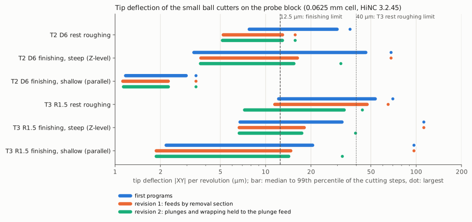
XY tip deflection per spindle revolution on the probe block (0.0625 mm cell, replayed on HiNC 3.2.45 for the NC-optimization study), over the cutting steps, on a logarithmic scale. Each bar runs from the median to the 99th percentile; the dot is the largest step. Blue: the first programs; orange: revision 1; green: revision 2. Dashed: the 12.5 µm finishing limit; dotted: the 40 µm limit of T3's rest roughing.
- Verdict. On the probe block, revision 2 brings the largest stress ratios, 0.38 (T2) and 0.35 (T3), inside C1's 0.5. C2 still fails by the letter. At its largest step T2's Z-level finishing bends 31.6 µm, T3's Z-level finishing 39.6 µm and its parallel finishing 32.3 µm, against 12.5 µm; T3's rest roughing bends 43.9 µm, against 40 µm. Only T2's parallel finishing stays under its limit. The acceptance verdict is the first programs': the revisions change only feeds, and their loads were judged on the probe block only.
- What is left. HiNC's step data puts T3's largest steps in revision 2 in the same groove
corner, x 22–34, y 5.4–8.6, and they are entries. T3's largest Z-level finishing step is
G1 Z-7.05 F300at X22.7 Y8.36: a straight plunge into the corner at the plunge feed, the contact 1.55 mm high and 1.17 mm wide, 74 N. T3's largest parallel finishing step isG1 Z-7.076 F300at X33.9 Y5.95, 58 N. T3's largest rest-roughing step is the first move of a level pass,X28.1 F900at Z−4.714, right after the descent at F300: contact 1.47 × 1.11 mm, 83 N, 43.9 µm. Holding the descents to the plunge feed was not enough for these steps; what is left to change is the entry. Apart from them, 10 % of T3's Z-level finishing cutting steps stay over 12.5 µm in both revisions (1,269 steps in revision 2). They lie along the rib groove's wall at y ≈ 8, over its whole height (the tool at z −7.0 to −4.5). There HiNC reads a contact 1.06 mm high and 0.43 mm wide (medians), while the rest roughing nominally leaves 0.04 mm. - Not tried. An entry from the side, in the air, instead of the plunge into the corner. A semi-finishing pass along the groove, or a slower feed for the whole operation. A ball smaller than the corner, such as R1, which would not cut on the whole arc; it is one more tool, left as a recommendation.
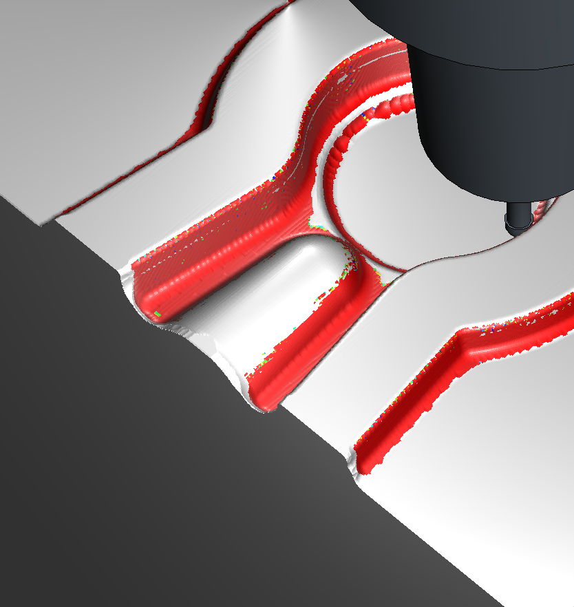
The pose at the top of the page, closer: T3's neck reaches into the impression below the chuck.
One rapid that grazed the stock
- Situation. The acceptance reported one
Play-RapidCut--Detected: “Rapid traverse at line 52852 (from step 202677) removed 0.0002461 mm3 of stock over 1 steps, cutting depth up to 0.625 mm”. The line is T1'sG0 Z-2.6at X−48 Y−24.5, over the lower lug, 1.15 mm above the next level. - Risk. Writing off a real rapid through stock as noise, or bending a criterion to pass.
- Noticed. The message inventory after the play.
- Resolution. The agent walked T1 again in line order on a 0.1 mm z-map: that rapid keeps 1.0 mm from the stock, every T1 rapid at least 0.99 mm. The contact is about an eighth of a 0.125 mm cell, a grid-level graze. A2 allowed no rapid-cut message, so A2 stays failed, as written.
- Evidence. One line, one step; no other rapid-cut message in the acceptance.
The agent's own mistakes, caught before the acceptance
| What went wrong | Risk | How it showed | Fix | Evidence it held |
|---|---|---|---|---|
| T1 fed straight from each helical entry to its loop's first point, across the gutter's land | a 3.0 mm gouge in the land | on the whole die; the trimmed window has no gutter ring | each loop starts at its point nearest the helix, reached by a link move | nothing more than a cell inside the design (D1) |
| Z-level finishing joined the tool-centre grid's nodes with straight lines | 0.035–0.05 mm below the design at the crease where the shank pocket ends | the agent's check along the normal | points every 0.25 mm lifted to the true drop-cutter height; links sampled every 0.1 mm | no move below the design |
| T3's links lifted only 0.5 mm | rapids through stock | HiNC at 0.25 mm: five Play-RapidCut--Detected |
links lifted 1 mm; rapids near the stock made feeds | no rapid-cut message from T3 |
| T3's neck Ø2.8 against its Ø3 ball | the neck rubbing the fresh wall | HiNC at 0.125 mm: a neck collision | neck Ø2.6 | no collision; 0.514 mm neck clearance |
| T2's finishing swept floors T1 had cut to size | wasted time | 19 of the operation's 34 min | only a band beside the rest | D1 passed with those floors left to T1 |
| T1's corner test took the block grown by the tool radius as a box | loops outside the block at every level | found before the acceptance | the true distance to the block | T1 1.5 min shorter, 22.7 m less rapid travel |
| A permission error from a lock query read as the shared lock being stuck | the acceptance ran for one minute beside another case's play before the agent stopped it | — | stopped, queued again, peer agents told | the acceptance ran alone under the lock |
Two more were fixed the same way: T3 crossed the die on 1,300 m of rapids because the gutter ring was one rest region (now 25 mm tiles, nearest next), and a multi-line header comment in the O line drew 3 warnings (the O line now carries only its first line).
A picture with the tool where it cuts
- Situation. The pictures of the cutter at work were to be taken by selecting a step after a play.
- Risk. No picture of the cutter in its holder at work, which the Showcase requires.
- Noticed. Selecting a step after the play left the tool where the program ended.
- Resolution. The trimmed case replayed one stage at 0.125 mm and paused at a chosen NC line, about 3 minutes per picture.
- Evidence. The pictures of T3 on this page.
Results and benefits
Measured on HiNC 3.2.43, one tool per run, on the whole lower die at 0.125 mm (3,722,141 steps) unless a row says otherwise (B3: the trimmed case at 1 mm; “probe”: the 12 × 11 × 12 mm block at 0.0625 mm).
| # | Criterion (written before the first play) | Result | Verdict |
|---|---|---|---|
| A1 | every line runs; every program cuts | 70,567 / 190,004 / 400,570 lines run; every operation touched the stock | pass |
| A2 | one Sys-Init--FileLines per program, no other message |
three Sys-Init--FileLines and one Play-RapidCut--Detected (0.0002461 mm³) |
fail |
| B1 | the agent's z-map: holder ≥ 5 mm, neck ≥ 0.5 mm | holder 11.48 mm; neck 4.06 mm (T2), 0.514 mm (T3) | pass |
| B2 | no Collision--Detected |
none | pass |
| B3 | negative control: T3 held 8 mm out raises a collision naming holder and workpiece | trimmed case at 1 mm, 15,281 Collision--Detected messages; the first, Collided(Workpiece,ToolHolder), at line 3306 (X42.4 Y−7.1 Z−8.687), where the agent's z-map put the first contact (42.3, −7.1, −8.69) |
pass |
| C1 | YieldingStressRatio below 0.5 for T2, T3 and 0.8 for T1, at every step |
largest 0.30 (T1), 0.83 (T2), 1.04 (T3); probe 0.84, 0.91. Beside it, revision 2 on the probe only: 0.38, 0.35 | fail |
| C2 | tip deflection ≤ 12.5 µm in T2's and T3's finishing, ≤ 40 µm in T3's rest roughing | largest 67.7 µm (T2) and 126.5 µm (T3) finishing, 99.4 µm rest roughing (the whole die replayed on HiNC 3.2.45 for the NC-optimization study); probe 68.1, 112.4, 70.0 µm, at the 99th percentile 26.6, 30.3, 53.4 µm (each tool's Z-level and parallel finishing pooled; the probe replayed for the same study). Beside it, revision 2 on the probe only: 31.6, 39.6, 43.9 µm, still over | fail |
| C3 | predictions (not judged) | T1 roughing up to 801 N, 337 N at the 99th percentile (predicted peak 300–450 N), power up to 1.40 kW (predicted 0.2–0.6 kW); T3 finishing 58.0 N (probe) to 75.0 N (0.125 mm) at the 99th percentile (predicted under 30 N); T3 rest roughing up to 130–187 N and 70–99 µm (probe to 0.125 mm; predicted 150–250 N, 50–80 µm); T3's loads from the probe's and the whole die's replays on HiNC 3.2.45 | reported |
| C4 | spindle power and torque ratios below 1 | power 0.37, torque 0.15 (T1) | pass |
| D1 | HiNC builds the difference; nothing over a cell inside the design; over a cell proud only where the agent's z-map leaves stock | 0 mm² inside; 0.87 mm² proud, all where the z-map leaves stock | pass |
| D2 | the agent's z-map, rest and gouge (reported) | rest at most 0.219 mm; no move below the design; the z-map's own −0.17 mm at steep wall tops comes from resampling T1's coarser map | reported |
| E1 | HiNC's time per program within ±3 % of the agent's | +0.04 % (64.86 against 64.83 min), +0.02 %, +0.01 % | pass |
| E2 | one half and the pair (reported) | 5.71 h (roughing 64.9 min, finishing 278.0 min); pair 11.43 h. Revision 2: 7.32 h and 14.64 h (T1 from the acceptance; T2 and T3 timed by HiNC on the whole die for the NC-optimization study, HiNC 3.2.45) | reported |
The shape, measured by the agent on HiNC's exported stock (5,495,546 triangles) rasterised at 0.1 mm along the normal inside the gutter (28,545 mm²): 1st percentile −0.005 mm, median 0.000 mm, 99th percentile +0.040 mm, deepest −0.034 mm, most proud +0.214 mm at (−53.1, −28.1), where the agent's z-map predicted its largest rest, 0.219 mm at (−53.4, −28.1).
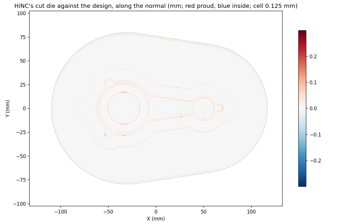
The agent's measurement of HiNC's exported stock along the normal: red is left proud, blue would be cut inside the design.
On the probe block (0.0625 mm, the cutting steps, replayed on HiNC 3.2.45 for the NC-optimization study), the first programs and the two feed revisions. The verdicts above are the first programs'; the revisions' loads were judged on the probe block only:
| First programs | Revision 1 | Revision 2 | |
|---|---|---|---|
| T3 Z-level finishing, largest tip deflection | 112.4 µm | 112.4 µm | 39.6 µm |
| T3 Z-level finishing, 99th percentile | 32.1 µm | 18.0 µm | 17.4 µm |
| T3 Z-level finishing, steps over 12.5 µm | 23.3 % | 10.2 % | 10.0 % |
| T3 Z-level finishing, largest force | 208 N | 208 N | 74 N |
| T3 parallel finishing, largest | 96.7 µm | 96.7 µm | 32.3 µm |
| T3 rest roughing, largest (limit 40 µm) | 70.0 µm | 65.1 µm | 43.9 µm |
| T2 Z-level finishing, largest | 68.1 µm | 68.1 µm | 31.6 µm |
| Largest stress ratio, T2 / T3 (limit 0.5) | 0.84 / 0.91 | 0.84 / 0.91 | 0.38 / 0.35 |
| One half, the agent's arithmetic | 342.8 min | 402.8 min | 439.1 min |
HiNC's own times of revision 2, read when the NC-optimization study played T2 and T3 on the whole die (HiNC 3.2.45), T2 121.98 min and T3 252.34 min, are within 0.03 % of the agent's arithmetic.
What the runs cost, on the shared server:
| Run | Cell | Steps | Run time | Peak memory |
|---|---|---|---|---|
| Whole die (T1 before the corner fix) | 1 mm | 3,727,657 | 37 min | — |
| Trimmed case | 0.125 mm | 926,397 | 21.7 min | 8.1 GB |
| Probe block | 0.0625 mm | 3,722,253 | 16 min | 8.7 GB |
| Whole die, acceptance | 0.125 mm | 3,722,141 | 77.7 min (T1 44, T2 10, T3 24) | 16.5 GB (predicted 18–20, at most 31) |
The case's own probe plays of the revisions, the whole programs over the block on HiNC 3.2.43, took 16.5 min (revision 1) and 17.3 min (revision 2, T2 and T3 only, 4,564,798 steps).
For a machining engineer. Before any steel was cut, HiNC confirmed that three tools finish the impression to the design within the grid, that 20 mm stick-outs clear the holders, the time of every program to 0.04 %, and a roughing power ratio of 0.37. It also found the weakest place: an R1.5 ball in the R1.5 corners of the rib grooves, bending about ten times its 12.5 µm limit. The corners are not the only place: over the whole die, 15 % of T3's Z-level finishing cutting steps are over the limit, and the D6 ball bends up to 68 µm (the whole die replayed on HiNC 3.2.45 for the NC-optimization study). Slowing the feed where the removed section is large cost 17.5 % more time by the agent's arithmetic. On the probe it lowered the 99th percentile, by about half in the Z-level finishing, but left the largest finishing steps unchanged. HiNC's step data showed what they were: descents into the groove at the cutting feed, and a ball wrapping a corner of its own radius. Holding those to the plunge feed made it 28 % more than the first programs. It brought the largest T3 finishing deflection on the probe from 112.4 to 39.6 µm (the probe replayed for the same study) and both stress ratios inside 0.5, but not under 12.5 µm. The largest steps left are entries into the corner; holding the descents to the plunge feed was not enough for them. What is left to change is the entry, from the side in the air, or the tool: a smaller ball for those corners costs one more tool.
For a teacher or a student. One part shows a closed-die forging die: parting plane, flash land and gutter, draft, a shrink allowance from two temperatures. It shows why a ball of a fillet's own radius loads its whole arc, why loads read on a grid coarser than a tool's allowance are checked on a finer one, and how a criterion can fail by the letter on a grid-level contact.
For someone weighing the approach. From one drawing and one photograph to the acceptance play of the whole die (three criteria failed, reported as such) took two days (30 September and 1 October 2026). The agent built the model, the die, the programs and their checks, on a height-field CAM an earlier case's agent wrote; three reviewer agents, with a refuter for each finding (fifteen agents in all), overturned its first forging. HiNC's time and shape matched the agent's own arithmetic and z-map, and its loads found the weak corner. The acceptance took 77.7 min and 16.5 GB on a shared server.
Honest limits
- The forging is a reading of one drawing, checked to 0.35 mm on it (the lugs apart) and to 0.4 % on the article's volume.
- The die is the agent's design, sized on a photograph. Flash thickness, gutter depth and walls and block height are chosen; FDAC is assumed; the shrinkage uses two expansion coefficients.
- Only the lower die was played. The upper one is the same shape and program.
- Outside the simulation: die filling, flash flow and forging force (the article simulated those), die life and heat checking, hard milling after heat treatment, polishing, ejectors, guide pins.
- Generic cutting data and machine. Loads are HiNC's model, not measurements.
- A coarse grid. Even the probe's 0.0625 mm is coarser than T3's 0.04 mm allowance; its loads are the better guide, not exact ones.
- Deflection is not in the shape comparison. D1 compares HiNC's removed shape with the design; it does not include the tip deflection HiNC reports.
- The revisions' loads are judged on the probe block only. They change only feeds, and the acceptance criteria were not judged again with them, so the acceptance verdict is the first programs'. Revision 2's times for T2 and T3 are HiNC's, from the NC-optimization study's plays of them on the whole die on HiNC 3.2.45, within 0.03 % of the agent's arithmetic.
- No blind build. No second agent rebuilt the case from its record.
What a reader can take to their own case
- Check a rebuilt part against a number the source states, and have it reviewed against the drawing. Here the volume was 2.1 % over, and the review found where.
- Size what the source leaves out on a photograph of the real thing, and mark it measured.
- Do not finish a concave fillet with a ball of its own radius. The whole arc cuts a thin layer: the section is small and the force large, so a feed rule by removed section does not see it. Here slowing the feed by section lowered the 99th percentile, by about half in the Z-level finishing, and left the largest finishing steps unchanged; holding descents and wrapping segments to the plunge feed brought the largest finishing deflection from 112.4 to 39.6 µm, still over the 12.5 µm limit. Use a smaller ball, or change how the tool enters the corner.
- Trace the largest steps to their NC lines before revising again. Here HiNC's step data showed that they were entries and wraps, not the cuts the first revision slowed, and then that the largest left were entries, with 10 % of T3's Z-level finishing steps along the groove wall still over the limit.
- Read a small cutter's loads on a grid finer than the acceptance grid, as close to its allowance as a probe block allows. Here 0.0625 mm against a 0.04 mm allowance was still coarser.
- Watch the share of steps in contact while a play runs. A tool that cut nothing still ends “Finished”. Writing the stock after each program lets you play one tool per run.
- Prove a silence. A negative control shows the collision check fires, and its first contact can be set against your own prediction.
- Keep a failed criterion failed, with the reason beside it.
- Check your CAM on the whole part. The worst gouge here, 3.0 mm into the flash land, lay outside the trimmed window.
Source and licence
- Source: Anna Dziubińska (Warsaw University of Technology), “The New Technology of Die Forging
of Automotive Connecting Rods from EN AB-71100 Aluminium Alloy Cast Preforms”, Materials 2023,
16(7), 2856, doi:10.3390/ma16072856 (PMC10095791). Search
terms if the link moves:
Dziubińska 2023 connecting rod EN AB-71100 die forging,ma16072856. - Licence: CC BY 4.0. The article states: “Copyright: © 2023 by the authors. Licensee MDPI, Basel, Switzerland. This article is an open access article distributed under the terms and conditions of the Creative Commons Attribution (CC BY) license (https://creativecommons.org/licenses/by/4.0/).” The licence gives the material as is, without warranty. No endorsement by the author or the publisher is implied.
- Attribution: “Forging drawing and die photograph: A. Dziubińska, Materials 2023, 16, 2856, doi:10.3390/ma16072856, CC BY 4.0. Die design and machining set-up by Tech Coordinate's agent.”
- What was changed: the article gives the forging drawing, the forging's volume, the process temperatures and the photograph. The three-dimensional forging is the agent's reading of Fig. 3; the die, its material, the machine, the tools and the programs are the agent's. Three figures here reproduce figures of the article: Fig. 3 whole, scaled down; its plan view, cropped, with the rebuilt outlines drawn over it; and Fig. 11a, cropped, beside HiNC's result. The other pictures are the agent's charts and renderings and HiNC simulations. This site offers no download: the reader fetches the article from the publisher.
See Also
- Connecting-Rod Forging Die, Optimized — HiNC's feed optimization on this case: the hand-revised programs 24.5 % shorter, and even the lowest feed leaves the R1.5 corner over its limit
- Showcase — the other cases and how a case page reads
- Replay Acceptance over the HTTP API — watching a play and accepting on evidence
- Memory Planning — sizing a run before it is built
- Cutter Geometry — holder profile, neck and stick-out
- A Mission That Resumes — recording the stock between programs