Jetson AGX Thor enclosure: a thin-walled aluminium housing in eight set-ups (3-axis)
- Original source
- Antmicro, Enclosure for Antmicro baseboard with NVIDIA Jetson AGX Thor, github.com/antmicro/jetson-agx-thor-baseboard-enclosure.
- Search keywords
antmicro jetson-agx-thor-baseboard-enclosure,cnc-milled-bottom-shell-al- Licence
- Apache License 2.0, given as is, without warranty. The parts are Antmicro's models, unchanged; the pictures below are rendered by HiNC from them, with the agent's stock, fixtures, tools and programs, or drawn by the agent's scripts from the models and HiNC's readings.
- Attribution
- Enclosure design (c) 2026 Antmicro, Apache-2.0, https://github.com/antmicro/jetson-agx-thor-baseboard-enclosure. Machining set-up by Tech Coordinate's agent (changes: stock, fixtures, toolpaths).
- About the case
- The aluminium enclosure of a computer baseboard for NVIDIA's Jetson AGX Thor, published as open hardware "optimized for compatibility with the popular 3-axis CNC machining process": a U-shaped bottom shell with 38.5 mm walls 3.5 mm thick, a top cover, and front and back panels whose 1.5 mm web carries vent grilles of 2.0 mm slots. The repository gives each part as a STEP model and a drawing; it gives no alloy, no tolerances, and nothing about how the parts are made.
The story
An AI agent wrote its own 2.5-axis CAM for the four parts and planned two set-ups for each: the inside from a thick blank held in a vice by a tab, then the part turned over onto a plug made from its cavity, the tab faced off and the outside, the chamfers and the holes machined. It took Al 6061-T6, a generic BT40 three-axis machine and a spindle that gives 12 kW at 6000 rpm but 3.7 kW at 12000. It chose fourteen tools, the two long-reach cutters from their maker's catalogue, put each in a shrink-fit or collet chuck at the shortest stick-out that reaches, and wrote eight Fanuc programs. Its CAM measures, on every pass, how far the neck, the holder and the whole tool stay from the part, the uncut stock and the fixture. It wrote seven pass criteria down before the first play, played the shell's first set-up alone three times, and then drove HiNC through its web API for the whole case at a 0.25 mm cell.
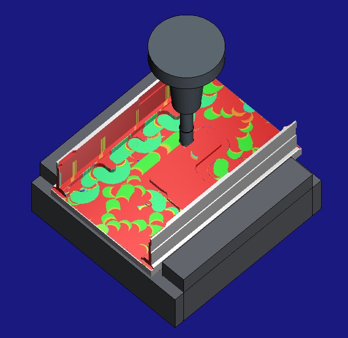
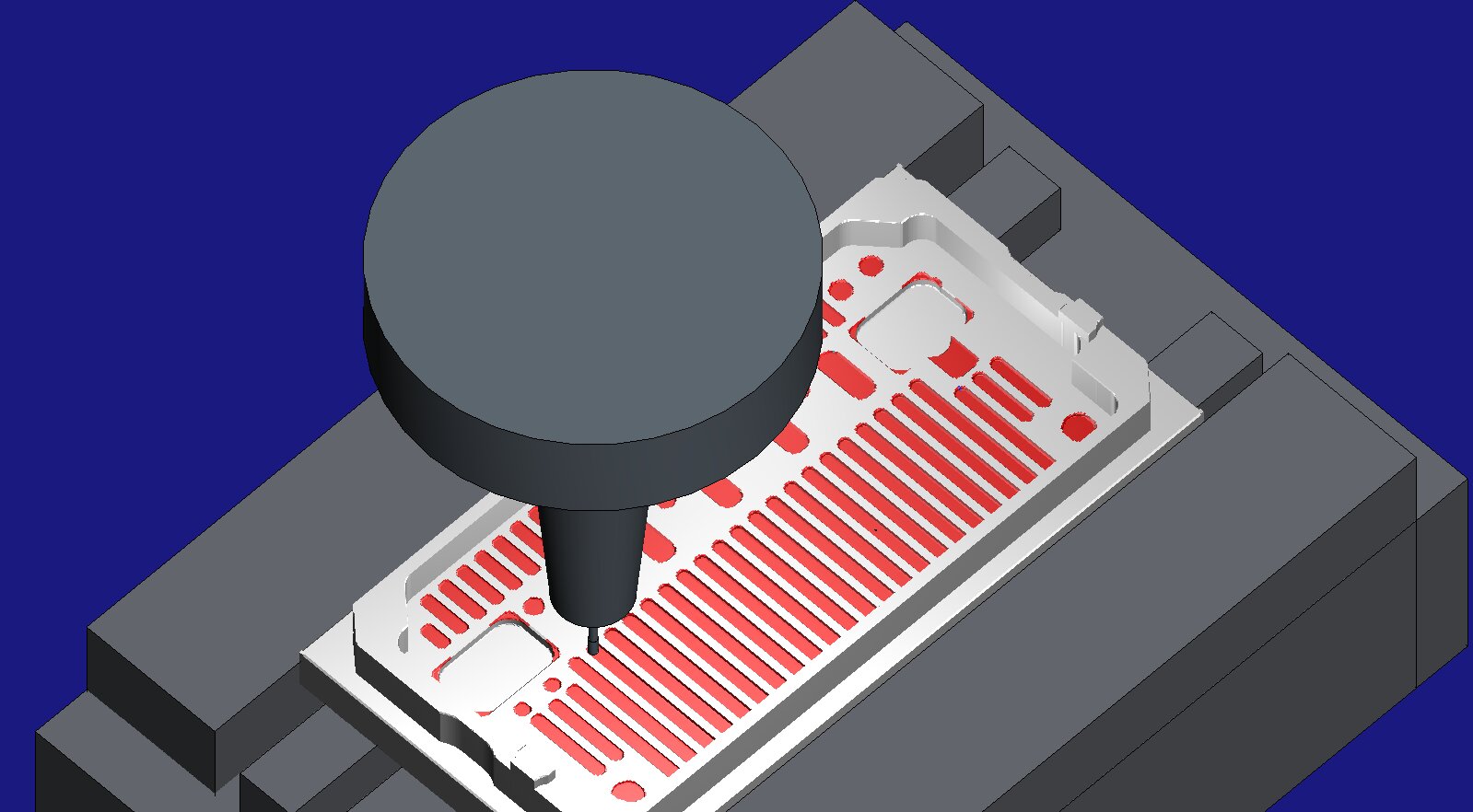
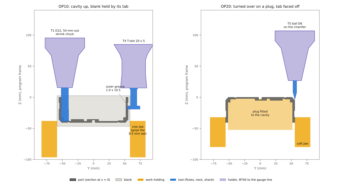
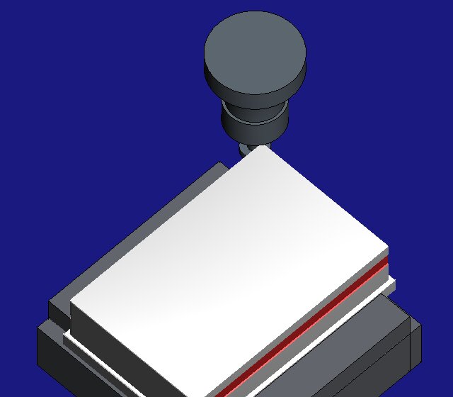
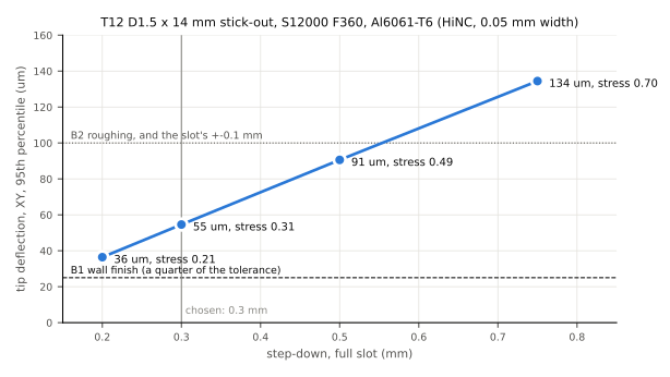
Rendered by HiNC from Antmicro's models (Apache-2.0) with the set-up Tech Coordinate's agent built. The section and the step-down chart are drawn by the agent's own scripts, from the models and from HiNC's readings.
Four of its eighteen dilemmas
A groove under the wall top
The shell's walls carry a 1.0 × 10.5 mm groove along the outside, below a wall top that stands 1 mm proud of it. Seen from above, the wall top hides the groove, so two vertical set-ups cannot reach it with an end mill; the agent found it by casting rays from every face up and down. A Ø20 × 5 T-slot cutter on a Ø10 neck cuts it from the side in the first set-up, while the cavity is still full and the 2.5 mm wall is backed by stock. The finished shell holds no stock beyond the limit in either groove.
A drill that moved before its length offset
Each drilling operation began with a retract to its clearance height,
and after a tool change that line came one line before G43. Without the length
offset, Z25 places the spindle nose, not the tip, and the drill went about 90 mm down. HiNC's
first play of the panels showed it: 42 collisions of the drill with the vice and of its
holder with the part, and 59 Z-stroke overruns, all in the last operation. On a machine that
is a crash on the first hole. The CAM now emits no Z move between a tool change and the
G43 line, which brings the tool to clearance height itself.
A grille cutter bending more than the slot's tolerance
The 2.0 mm slots are cut with a Ø1.5 two-flute cutter, 14 mm out of its chuck. In two levels of 0.75 and 0.95 mm, HiNC showed its tip bending 144 µm at the 95th percentile, at 0.88 of the tool's yield stress: slot walls out of their ±0.1 mm and a tool close to breaking. The agent played a small trial: the same cutter slotting solid stock at four step-downs. The bending followed the step-down almost in proportion, about 180 µm per millimetre (134, 91, 55 and 36 µm at 0.75, 0.5, 0.3 and 0.2 mm). At 0.3 mm a level the cutter bends 62 µm at the 95th percentile, its stress peaking at 0.53 of its yield stress; the grilles take 88 and 120 minutes instead of 34 and 40.
Two places no pass reached on the cover
The cover's play finished clean, yet its finished part, exported from HiNC and compared with the model, was only 95.8 % within the limit. Two areas were left: the lower half of the 49° outer bevel, 5 mm tall where the program had roughed 3 mm and ball-finished 2.1 mm; and at both ends a 2 mm band beside a small lug, too narrow for any tool inside the outline. The bevel is now cut to its full depth, and the band from outside the outline, the cutter's edge reaching in while its centre stays in the open. The cover then came to 99.6 %, and the same check found the panels' curved ends and an end notch short in the same way.
The other fourteen are in the full record, among them a plug that filled the blind holes the drills had to reach, a spindle asked for 3.3 times its rating at 12000 rpm, a 1.4 mm neck passing 0.05 mm from a tall wall, and rapid moves that grazed finished walls.
The result
At a 0.25 mm cell, all eight set-ups ran to the end in HiNC, every one of their 103 operations touched the stock, and no play reported a rapid cut, a collision or a stroke overrun. HiNC's machining time came within 1 % of the agent's own estimate: 382.9 minutes for the four parts against 381.5, that is 59.5 minutes for the shell, 60.3 for the cover, 115.6 and 147.5 for the front and back panels. The finished parts lie 99.3 to 99.6 % within 0.1 mm plus half a cell of the models; the rest is stock the plan leaves on purpose (R1 corners 38 mm deep left at R3, four holes along X in the end faces) and drill points in flat-bottomed blind holes. Six of the seven criteria written before the first play passed. The one that failed asked the long cutters to bend no more than 25 µm anywhere on a finishing pass: at the 95th percentile they stay within 22 µm, the shell's chamfers aside (35 µm), but single steps reach 28 to 56 µm where a pass meets more stock than its 0.3 mm allowance. The plays took 97 minutes on a shared 32-thread server, with 34 GB of memory at the peak. Everything is simulated; no part was cut.
| Key number | What it is |
|---|---|
| 382.9 min | HiNC's machining time for the four parts in eight set-ups, against the agent's own estimate of 381.5; each set-up 0.1 to 1.0 % over its estimate |
| 59.5 / 60.3 / 115.6 / 147.5 min | the shell, the cover, the front and the back panel; on the panels the grille alone takes 88 and 120 minutes |
| 103 of 103 | operations that touched the stock in the acceptance; no play reported a rapid cut, a collision or a stroke overrun |
| 99.34–99.56 % | of each finished part's surface within 0.1 mm plus half a cell of the model; the rest is stock the plan leaves and drill points in flat-bottomed holes |
| 3.3 → 0.79 | the spindle power ratio the Ø12's first program asked in full-width entries at 12000 rpm, and the highest in the whole acceptance once it ran at 8000 rpm |
| about 180 µm per mm | the Ø1.5 grille cutter's bending per millimetre of step-down in a full slot; at 0.3 mm a level it bends 62 µm at the 95th percentile, its stress peaking at 0.53 of its yield stress |
| 22 µm / 28–56 µm | the long cutters on finishing passes: the 95th percentile (the shell's chamfers aside, at 35 µm), and the largest single steps; the criterion that failed asked for 25 µm at every step |
| 97 min, 34 GB | the plays of the whole case on a shared 32-thread server for 6.4 hours of machining, and the instance's peak memory |
NC optimization of this case →
What it brought
- For a machining engineer: the times per part; a step-down rule for a 1.5 mm cutter (about 180 µm of bending per millimetre); and, before any cut, the drill crash, the overloaded spindle, the bending cutters, the grazing rapids and four areas the programs never reached.
- For a teacher or a student: a complete two-set-up plan for a thin-walled housing: an undercut reached from the side while the wall is still backed, a plug that leaves the blind holes open, a neck clearance kept against the stock still standing, and the order in which the checks found each problem.
- For someone deciding whether to use an agent with HiNC: from four models and their drawings, with no program to start from, to eight programs that pass six of seven criteria fixed in advance; the CAM, the set-ups and the checks are the agent's work. The criterion that failed is reported as failed. No second agent rebuilt the case.
Read the full case record: Jetson AGX Thor enclosure
The source and its backup
| Case | Original files | Backup |
|---|---|---|
| Jetson AGX Thor enclosure | Antmicro's repository (STEP models and drawings) | Showcase-Antmicro-Thor-Enclosure.zip |
The zip holds the case's SOURCE.md, which states what was
changed; Antmicro's STEP models, drawings, README and the Apache-2.0 LICENSE as delivered;
and the agent's work: its CAM scripts, the numbers file with every tool, set-up and pass criterion, the
eight programs, the 1.5 mm cutter's step-down trial, and the acceptance results. The fixture meshes and
the programs split per tool are left out: the scripts in the zip write them again.