Jetson AGX Thor enclosure: HiNC's feed optimization takes 76 minutes off three set-ups, and 37 % off a grille that looked at its limit (3-axis)
- Original source
- Antmicro, Enclosure for Antmicro baseboard with NVIDIA Jetson AGX Thor, github.com/antmicro/jetson-agx-thor-baseboard-enclosure.
- Search keywords
antmicro jetson-agx-thor-baseboard-enclosure,cnc-milled-bottom-shell-al- Licence
- Apache License 2.0, given as is, without warranty. The parts are Antmicro's models, unchanged; the pictures below are rendered by HiNC from them with the agent's stock, fixtures, tools and programs, and the charts are drawn from HiNC's per-step results and the optimizer's per-step log.
- Attribution
- Enclosure design (c) 2026 Antmicro, Apache-2.0, https://github.com/antmicro/jetson-agx-thor-baseboard-enclosure. Machining set-up by Tech Coordinate's agent (changes: stock, fixtures, toolpaths and their optimization).
- About the case
- Three accepted programs of the Jetson AGX Thor enclosure, an open-hardware aluminium housing: the first set-ups of the bottom shell and the top cover, roughed and finished with two Ø12 mm end mills on a spindle that gives 11.8 kW at their 8,000 min⁻¹, and the back panel's grille, 26 slots cut with a Ø1.5 mm long-neck cutter in two hours. Here HiNC's feed optimization takes those three programs over.
The story
The enclosure's acceptance had left three questions a shop would ask. The two Ø12 programs run the agent's cautious CAM rules — 0.08 mm per tooth, and half feed on every ramp entry and on the full-width first lap of every level — and in their finishing passes the long cutters bend past the case's 25 µm limit wherever a pass meets more stock than its allowance. And the grille cutter, at the case's 0.25 mm grid, read its stress right at its target, as if no feed were left. An AI agent handed the three programs to HiNC's feed optimization, which rewrites the feed of every line from the loads it reads at each step, and asked: is the spindle or the chip the limit of the roughing, can the finishing be held within 25 µm, and is the grille really at its limit? It wrote its criteria, settings and decision rules down first, tried the chain on short stretches of each program and on one grille slot at three grids, amended the plan in writing where the trials showed it wrong, and then optimized and replayed each program whole: V1 holds every finishing line at its programmed chip, V2 also steers the finishing by its measured bend, V3 is the grille. Every number here comes from these plays.
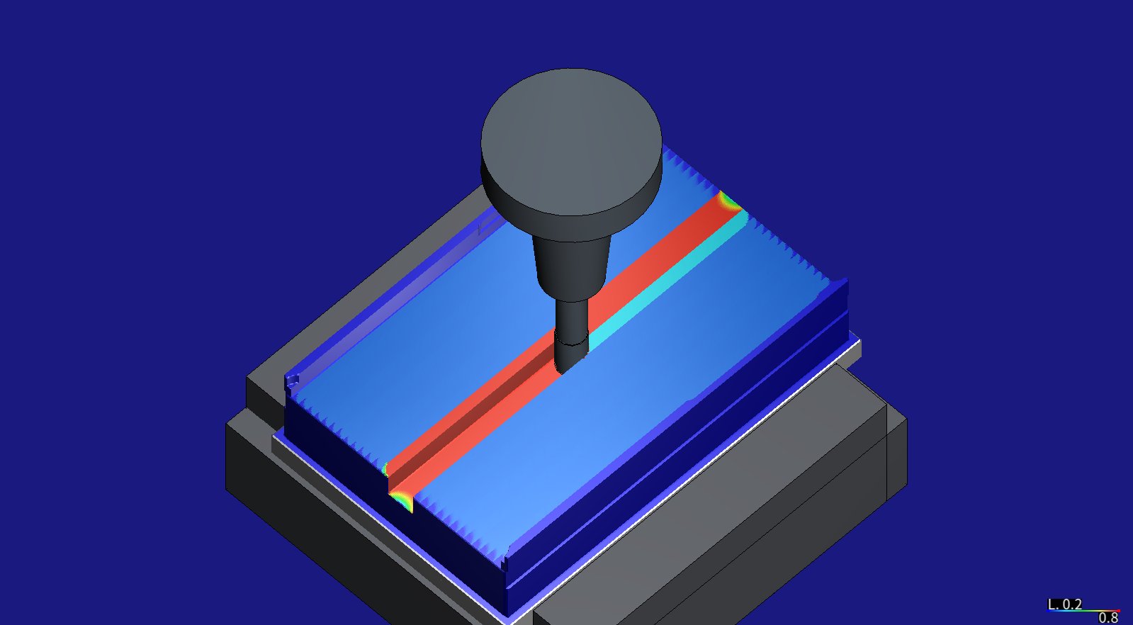
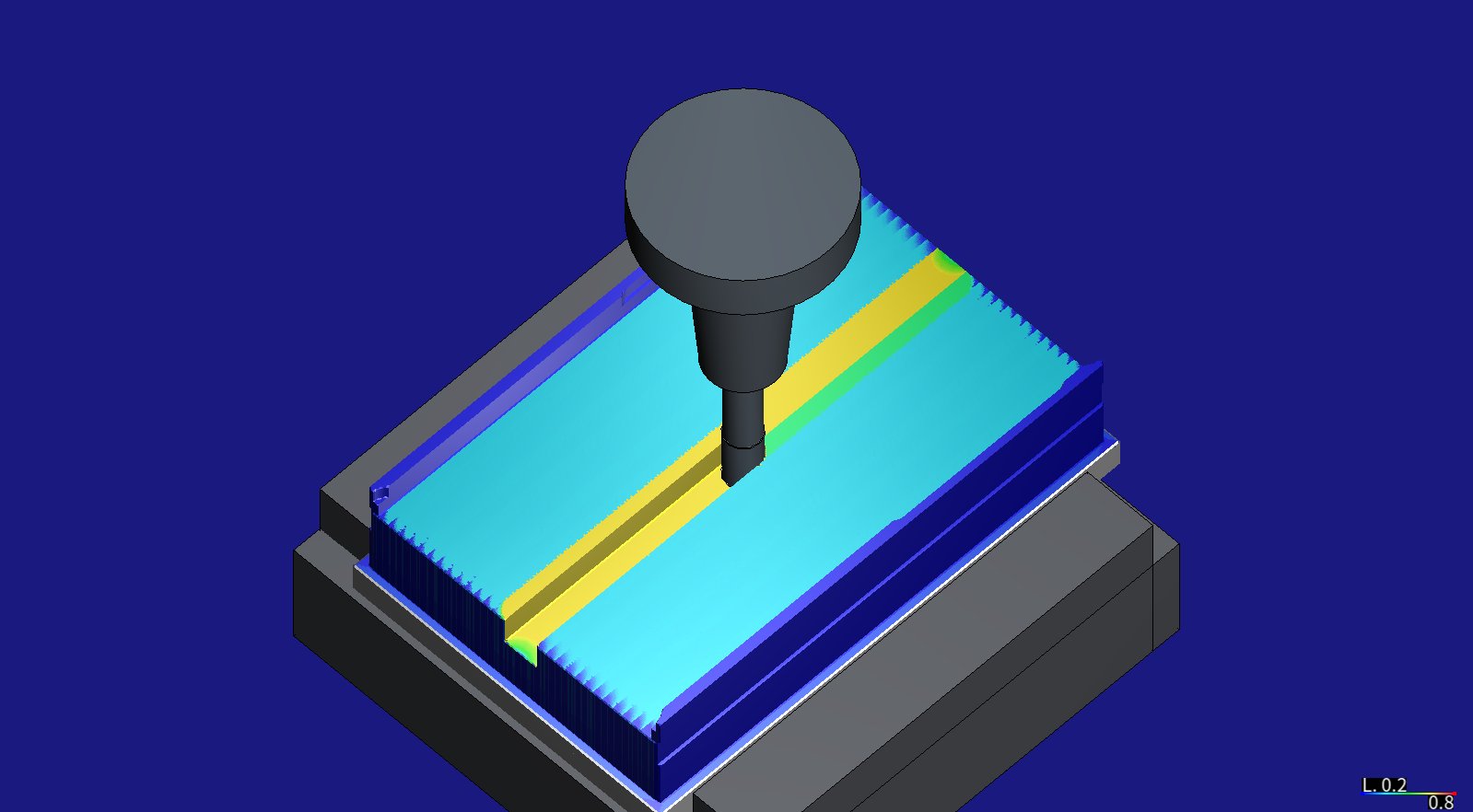
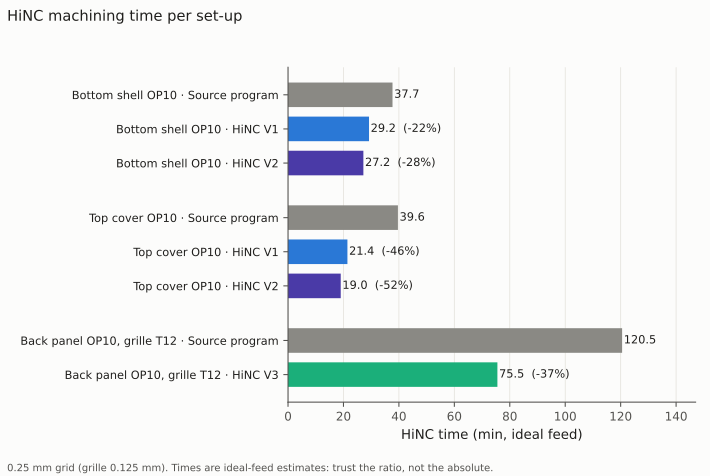
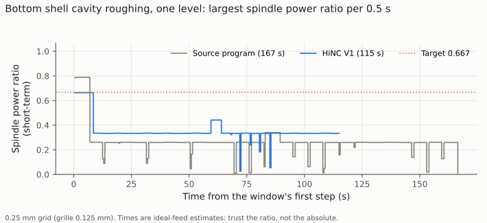
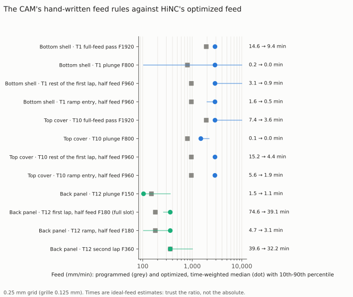
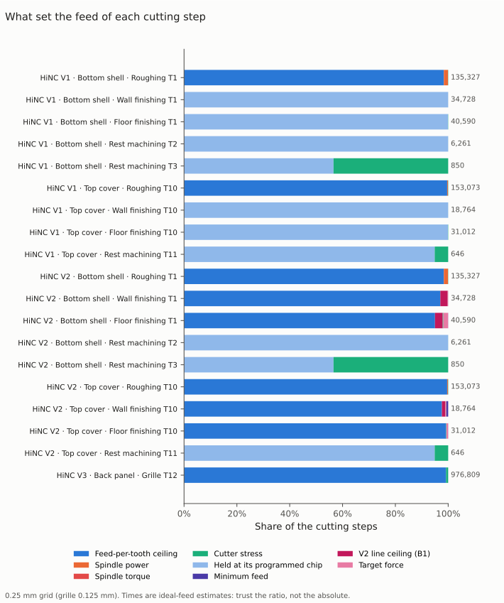
Pictures rendered by HiNC from Antmicro's models (Apache-2.0) with the set-up Tech Coordinate's agent built. The charts are drawn from HiNC's per-step results and the optimizer's per-step log; the times are ideal-feed estimates, so compare the ratios rather than the absolute times.
| Key number | What it is |
|---|---|
| 37.7 → 27.2 min | the bottom shell's first set-up with V2 (−27.9 %); 29.2 min (−22.5 %) with the finishing held as programmed |
| 39.6 → 19.0 min | the top cover's first set-up with V2 (−52.0 %); 21.4 min (−46.0 %) with the finishing held |
| 120.5 → 75.5 min | the back panel's grille stage (−37.3 %) |
| 76.1 min | saved on the three programs, 197.9 → 121.7 min: 60.5 of it cutting, 15.6 feed through air |
| 98.4 / 99.6 % | of the Ø12 roughing steps at the 0.12 mm per-tooth ceiling the agent allowed: the chip, not the spindle, is the limit |
| 0.788 → 0.664 | the largest spindle power ratio in the shell's roughing, against a target of 0.667 of the short-term rating; its 2,076 steps over the target fall to none |
| 72 % | of the cover's roughing time in the CAM's half-feed laps, which the optimizer runs at three times their feed |
| 36.5 → 24.2 µm | the cover's largest finishing bend with V2, against the case's 25 µm; the shell's 42.6 → 26.7 µm |
| 0.338 → 0.333 | the grille cutter's largest stress ratio, at its target, with 99.2 % of its steps at the programmed chip |
| 1 µm, 0.001 % | the shape: the agent's height map of the stock alike within 1 µm on all but one of its two million nodes, and HiNC's exported parts within 0.001 % in volume |
| 12.5 min, 57 GiB | server time and peak memory of one optimization play of a Ø12 program; its replay under 8 min and 4 GiB |
Four of its twenty dilemmas
Two chips in one finishing pass
The CAM enters each finishing level with a ramp and a first lap at half feed, then runs the same lap again at full feed. One ceiling per segment would have doubled the half-feed lap — the one that takes the allowance — and in a trial the cover's finishing bent 43.6 µm instead of 36.5. So every finishing line is held at its own programmed chip: a load can slow it, nothing speeds it up, and the finishing cuts exactly as programmed.
A target force that skips the ramps
The optimizer has no deflection criterion, so the agent carried the 25 µm as a target force from each cutter's compliance. Step by step it found the target lowered 69 of the 93 level steps over it and none of the 92 on ramps, where the largest bends sit. So V2 adds a ceiling for every finishing line from that line's own bend: 7,195 of the shell's 7,392 lines rise toward the catalogue's finishing chip, 133 are slowed. The cover met 25 µm; the shell came within 2 µm.
A grille that only looked finished
At the case's 0.25 mm grid HiNC read the Ø1.5 cutter at its stress target. Played on three grids, the first slot's half-feed laps showed the same median stress everywhere but a tail at 0.25 mm 26 to 42 % higher: the grid's, not the cut's. By a rule written before the trials the agent ran the grille at 0.125 mm, where 99 % of the steps reached the programmed chip: 37 % less time at the same target.
Faster than predicted
The plan predicted the cover at −15 to −30 %; it came out at −46 %. The comparison with the CAM's own rules explained it: 72 % of the cover's roughing ran in half-feed laps — ramps and the full-width first lap of each level — which HiNC reads far under its targets and sends at three times their feed. A general "half feed at full width" rule was the largest single waste in the programs.
The other sixteen are in the full record, eight of them smaller ones in a table; among them hundreds of script messages in a clean replay that turned out to be one harmless pattern, a move at the air feed over a 0.06 mm³ sliver narrower than HiNC's grid, plunges read as the cutter's whole face, and an optimization play that needed 57 GiB on a server shared with live services.
The result
Every optimized program replayed to its last line with no collision, stroke or rapid-cut alarm, and left the same part: the agent's own height map of the stock agrees within 1 µm on all but one of its two million nodes, and HiNC's exported parts within 0.001 % in volume. The three programs lose 76 minutes. The Ø12 roughing runs at the chip ceiling the agent allowed, 1.5 times its programmed chip; only the full-width cut that opens each level, which the source program had run above the spindle's target, is slowed. The finishing is held exactly as programmed in V1; in V2 it is steered by its own measured bend, runs faster than in V1, keeps the cover within 25 µm and leaves the shell's worst step at 26.7 µm. And the grille that looked finished gave 37 %. Everything is simulated; no part was cut.
What it brought
- For a machining engineer: 76 minutes off three programs without touching a toolpath; the spindle's real power curve read against every cut, showing that the chip ceiling, not the spindle, sets the roughing speed; a measured answer to what the CAM's cautious habits cost; and a finishing pass first protected, then sped up within its bend limit.
- For a teacher or a student: why a coarse grid can invent a limit, why a target has to be checked where it acts — a ramp is not a level cut — and how a per-step log tells which criterion set each feed.
- For someone deciding whether to use an agent with HiNC: three programs taken through ten whole-program plays and 27 small ones in about 105 minutes of server time; criteria and decision rules fixed first, the plan changed only by written amendments, and every criterion that failed reported with its reason.
Read the full case record: the enclosure's NC optimization
How the parts, their set-ups and these programs were made: Jetson AGX Thor enclosure.