NASA HECC Centrifugal Impeller: Simultaneous Five-Axis Machining from Published Blade Coordinates
An AI agent took the published blade coordinates of a NASA compressor impeller, with no unit and no
model, stock, machine or tool path, and simulated machining it in HiNC. Its Python scripts lofted the
part, made a turned blank and a generic five-axis machine, and wrote the five-axis tool path. Through
HiNC's web API, HiNC played the path with a tapered ball end mill in a shrink-fit holder, checked it,
computed the cutting load, compared the result with the design and posted it as Fanuc NC with
G43.4 (tool centre point control). HiNC's physics predicted that the first path would break the
tool, and the agent rewrote it; HiNC's product owner questioned one lift on the 3D view, and the fix
saved a tenth of the simulated machining time.
Everything here is simulated: no part was cut on a real machine. Each dilemma below gives the risk, how it came to light, the resolution and the evidence that it held. The built project was the agent's working material and is not distributed.
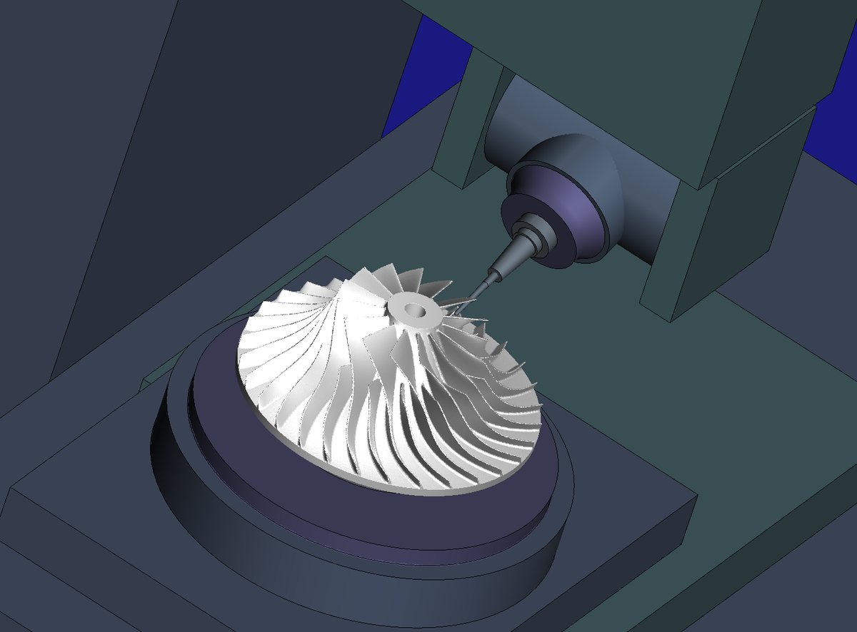
The impeller after the whole job: the tapered ball end mill, 92 mm out of its shrink-fit chuck, re-traces a finished wall near the inlet. Rendered at 0.5 mm on the path before the local links (same cut points), in a run that cut nothing. Captured on HiNC 3.2.39.
The case
The source is the supplement of NASA contractor report CR-2014-218114/REV1, High Efficiency
Centrifugal Compressor for Rotorcraft Applications (G. Medic et al., United Technologies Research
Center, for NASA Glenn Research Center). Its folder AppendixE.4_HotCoordinates/ gives a hub line
(the body the blades stand on) and a shroud line (the casing contour over the blades), both as x r
pairs, and eleven sections of each of the two blade shapes as X, R*THETA, R triples. The part has
15 main blades and 15
splitters (shorter blades starting partway down a passage, the channel between two blades). No file
names a unit.
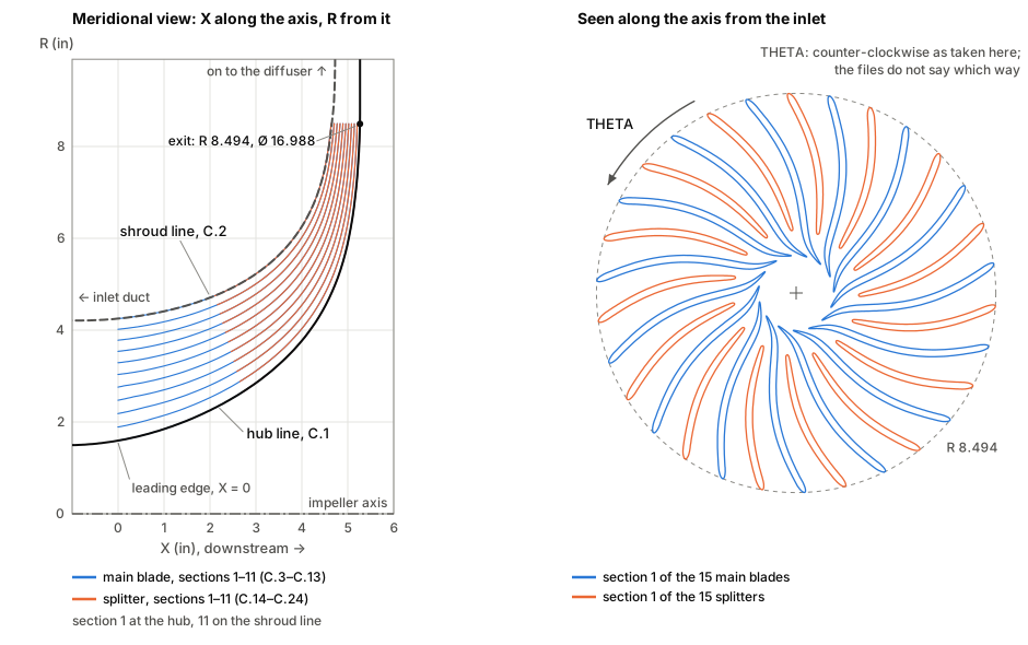
The 24 tables as the folder gives them, in the files' own numbers (inches, as the first dilemma shows): the hub line has 350 points, the shroud line 310, and each blade section 201, from the hub (section 1) to the shroud line (section 11). On the right THETA is taken counter-clockwise seen from the inlet, as the agent's model takes it; the files do not say which way it runs.
The report says more than the files carry: the real part was Ti-6Al-4V with a compound blade-hub fillet; its 0.012 in tip clearance is not in the sections; and the coordinates are the hot shape at the design speed of 21,789 rpm, the cold shape for manufacture not being supplied. The direction of THETA, where the part sits, how it is held, the controller and the tool are not stated, and there is no solid model, no blank and no tool path. HiNC has no CAM, so the agent acted as the CAM programmer, writing cutter-location (CL) files — tool-tip points with tool-axis vectors, what a CAM system hands its post-processor — and used HiNC as machine, inspector and post-processor.
What the agent built
Everything went through HiNC's web API, following Project Construction, Driving the Web Service over HTTP, Cutter-Location Playback and Replay Acceptance over the HTTP API. Each value is marked read (stated by the source), derived (worked out from it), chosen (by the agent where the source is silent) or measured (in a run on HiNC 3.2.39).
| Item | Value | Basis |
|---|---|---|
| Units, size | inches at 1:1; 431.8 mm across the tips; 15 + 15 blades | Units and size derived; 1:1 chosen; blades read (Figure 58) |
| Design model | blades lofted through the sections on a revolved hub, trimmed to the shroud line | Sections read, loft derived; hub nose, 12 mm back disc, Ø30 mm bore chosen: the data give only the flow path |
| Blank | the shroud line revolved, closed by the inlet plane and a 215.9 mm rim, as if turned; it and the design model span 431.8 mm across and 60 to 212.11 mm above the table (152.1 mm tall) | Chosen, so milling only opens the passages |
| Fixture | Ø280 × 60 mm chuck plate, Ø29.6 mm boss in the bore up to 85 mm above the table; 1,080 triangles | Chosen |
| Machine | generic: rotary table C, swivel head B; X ±900, Y ±600, Z −1000 to +400 mm, B ±110°, C endless | Chosen |
| Program zero | table top centre, Z up the impeller axis; G54 (0, 0, −700) | Chosen; G54 measured |
| Controller, material, spindle | Fanuc (HiNC posts CL as Fanuc NC); AA7075; generic 24,000 rpm, run at 12,000 | Chosen; the real part's titanium read |
| Tool | tapered ball end mill R3, 2° half-taper, 70 mm flute, Ø12 shank from 88.9 mm; 3 flutes, carbide | Chosen: thin at the tip, stiff above; 88.9 mm derived |
| Holder, stick-out | shrink-fit chuck, Ø24 nose, 102 mm gauge length; 92 mm out, tool length 194 mm | Chosen; 194 mm measured |
| Operations | roughing in levels 2.5 mm apart, 0.5 mm left, 1,800 mm/min; every blade wall before any hub, since a hub pass runs along two walls (contours 1 mm apart, axis 3° off the wall, flank 0.55 mm off other blades); each hub along flow lines at most 1 mm apart; finishing at 2,400 mm/min | Chosen |
| Tool axis | 12° lean downstream in roughing and hub finishing where it clears; in finishing at most 4° of turn between cut points | Chosen after HiNC's physics |
| Tool path | 621,840 moves roughing; 848,914 walls and 14 hubs; 13,901 the last hub | Measured |
| Mission | stages A roughing, B walls and 14 hubs, C last hub with physics, each ending in a record of the part; collisions on; motion resolution 1 mm and 15°; comparison and NC conversion after; three more lists, unticked for the whole job, replay the posted NC (D), run the collision probe (Z) and play the trial (T) | Chosen (A Mission That Resumes); 2,298,853 steps measured |
| Resolution | 1 mm for the reference run, 0.5 mm for the pictures (the cube edge of the simulated stock) | Chosen (Mesh Resolution) |
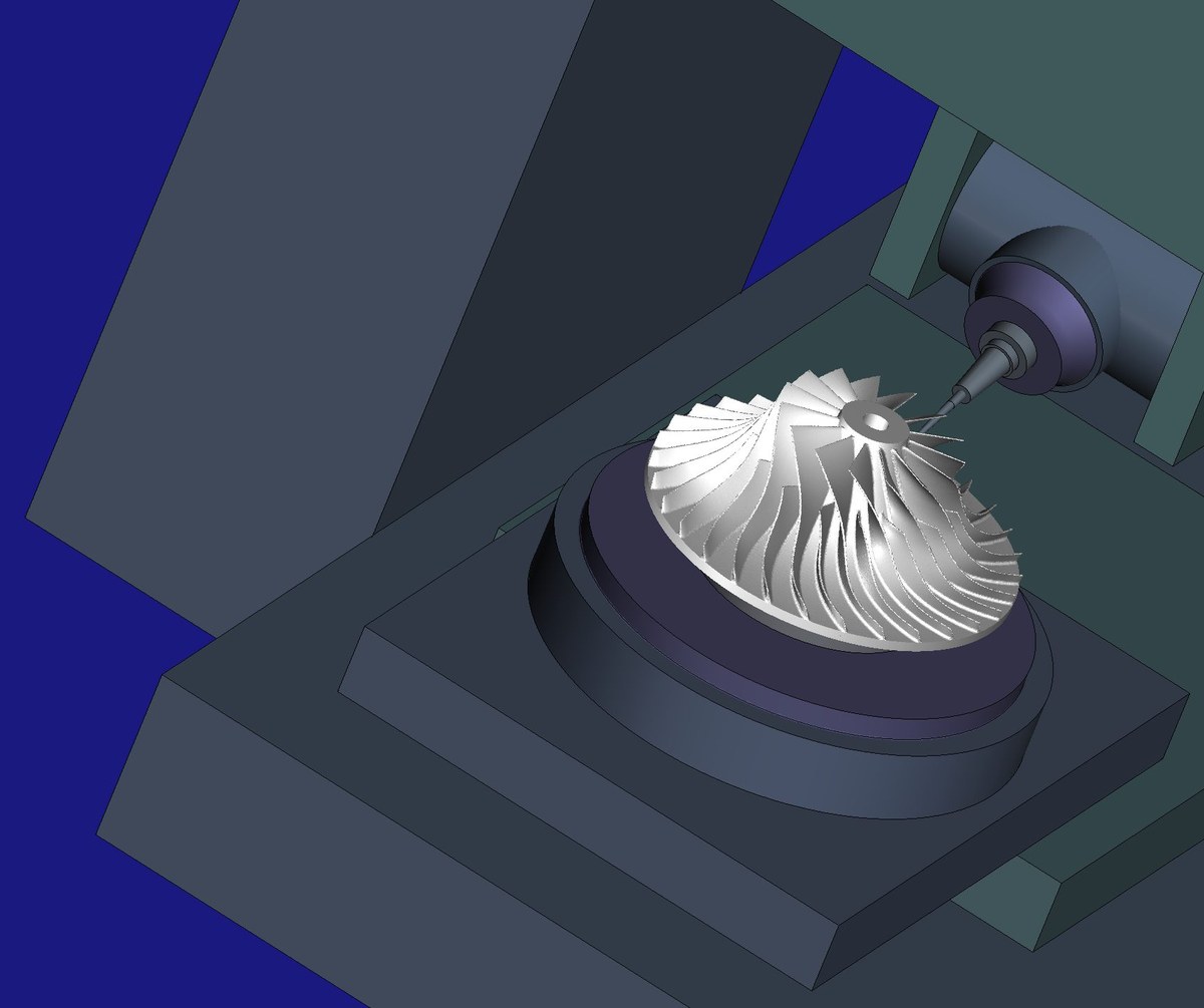
The machine the agent's script builds from boxes, cylinders and cones: the column, the ram with the swivel head B and the spindle, and the rotary table C on its X and Y slides with the Ø280 mm chuck plate. Rendered at 0.5 mm in the same run as the picture at the top of the page. Captured on HiNC 3.2.39.
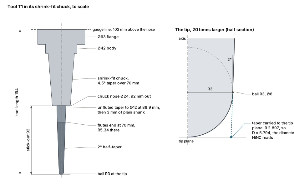
Tool T1 drawn to scale from the numbers in the table below, and its tip twenty times larger: carried down to the tip plane, the 2° taper meets it at R 2.897, so D = 5.794 mm, while the ball is 6 mm across. D = 6 does not fit this profile: HiNC refuses it at the tool change and names D = 5.794.
The tool and the holder as the agent entered them in HiNC's tool house:
| Item | Value |
|---|---|
| Profile | ball R3, 2° half-taper, 70 mm of flute; entered as D = 5.794133 mm, the taper line carried to the tip plane |
| Above the flute | the unfluted taper runs on to the Ø12 shank at 88.86 mm; the shank is modelled 40 mm into the chuck |
| Fluting | 3 flutes, constant 30° helix, radial rake 8°, radial relief 8° |
| Edge | hone radius 15 µm |
| Material | carbide, HiNC's WC-Co10-600nm cutter material, for the flute and the shank |
| Holder | generic shrink-fit chuck for a Ø12 shank, profile (Z, R) from the nose: (0, 12), (70, 17.51), (70, 21), (82, 21), (82, 31.5), (102, 31.5); that is a Ø24 nose, a 4.5° taper, a Ø42 body and a Ø63 flange, gauge length 102 mm |
| Stick-out, tool length | 92 mm; 102 + 92 = 194 mm |
| Offset table, for the posted NC's replay | row 1 taken from the tool house: length 194 mm, radius 5.3415 mm (the profile's largest, at the flute top) |
The tool path the agent's script writes: one passage's cut points per operation, then the programs of the whole job, every passage being the first one turned by 24°:
| Operation | One passage | Program: lines (moves) |
|---|---|---|
| Roughing | 41,161 cut points, 37.6 m | roughing of passages 1–15: 627,472 (621,840) |
| Wall finishing, around one main blade and one splitter | 43,206 cut points, 30.1 m | the walls of all 30 blades, then the hubs of passages 1–14: 852,646 (848,914) |
| Hub finishing | 13,804 cut points, 14.6 m | the hub of passage 15: 13,963 (13,901) |
| Trial | roughing, wall and hub finishing of passage 1 | played alone before the whole job: 99,611 (98,977) |
How the agent managed the work
- Small before large. CL played on the five-axis machine (HiNC solving all five axes), posted to
G43.4NC and replayed first ran cleanly on a small cone-frustum test; one passage was then timed at 1, 0.5 and 0.25 mm, and a trial of passage 1 ran before the whole job. - Pass criteria. Replay Acceptance's checks (steps, lines executed, material touched, comparison built); messages by id and count, with no collision, rapid through material or stroke limit; no tool position dropped by the generator; the physics passage's load read per step against HiNC's breakage rule. Reference numbers were then measured on a freshly restarted HiNC and fixed for a rebuild.
- No blind build. No separate agent rebuilt the case; the nearest check was a reviewer reading the instruction as an agent with only the case's files would.
- Adversarial review. An early review forced three changes to the path and the export (dilemmas below). Three later rounds, each reviewer paired with a refuting agent, confirmed 48 findings (39, 5 and 4) in the build instruction and source notes, all corrected; the heaviest: a probe whose figures could not be reproduced, and no step from the trial to the whole job.
- A shared server. The agent ran its own HiNC instance on a 32-core server shared with others, restarting it before each measured run so that a memory peak belongs to that run alone; the reference run uses 1 mm and the pictures 0.5 mm, and no whole-part run went finer than 0.5 mm.
- Where a person stepped in. HiNC's product owner, who set the task, ruled that every tool sits in a realistic holder at the shortest stick-out that is enough, so the agent defined a shrink-fit chuck and shows it in every picture; ruled out client material and unlicensed assets, so the agent generated its own machine; asked for builds from the public documentation; and picked one lift on the canvas (“The owner saw strange lifts”).
The dilemmas
Unless a dilemma says otherwise, its numbers were measured on HiNC 3.2.39 on a 32-core server at 1 mm.
The coordinates have no unit
- Situation. The files give an exit radius of 8.49376, with no unit.
- Risk. A part 25.4 times too small or too large.
- How it was noticed. At once: no file names a unit.
- Resolution. Compared with the report's Table 2, the coordinates are inches; used at 1:1.
- Evidence it held. Three diameters match the table to its last digit: 2 × 1.5949 = 3.190, 2 × 2.6574 = 5.315 and 2 × 8.49376 = 16.988 in.
A 4.93 GB download for 0.2 MB of data
- Situation. The supplement is one 4.93 GB zip; the case needs 25 files, about 0.2 MB.
- Risk. Downloading 4.93 GB for them.
- How it was noticed. The file size on the record page.
- Resolution. The server did not advertise range support but answered a ranged request with a partial response, so the agent read the zip's table of contents and the 25 entries by byte range.
- Evidence it held. About 5 MB came down; every entry passed its CRC check, and the source notes list each file's SHA-256.
What the licence allows
- Situation. The record says Public Use Permitted, but the data belong to a contractor report, not a U.S. Government work, and the record defines no scope and names no licence or rights holder.
- Risk. Overstating the right to use and redistribute the files.
- How it was noticed. The agent's first notes called the data not copyrighted; the record's API
fields (
belongsToUsGov: false,licenseType: NO) say no such thing. A later review had the notes state what the determination leaves undefined. - Resolution. The record is quoted field by field, the authors credited in a fixed line, and the backup copy rests on this reading and is removed at the rights holder's request.
- Evidence it held. The case takes only the folder stated to be “not subject to the EAR or the ITAR”, and none of the supplement's export-marked files.
Which five-axis machine?
- Situation. HiNC's library has only a three-axis generic chain; its five-axis models are third-party machines not licensed for this use, and its one holder file carries a third party's name.
- Risk. A vendor's machine on a public page, or no machine at all.
- How it was noticed. Going through the library before building.
- Resolution. A script generates a table-C, head-B machine from boxes, cylinders and cones, the same file byte for byte on every run; the holder is a Z–R profile in the project (Building Virtual Machine Tools).
- Evidence it held. HiNC bound all five axes, the program-zero call put the spindle nose 700 mm above the table as built, and the whole job raised no stroke-limit message.
How short can the stick-out be?
- Situation. The owner asks for the shortest stick-out that is enough; a shrink-fit grips only the cylindrical shank, which the taper reaches at 88.9 mm. The deepest passage is 67.5 mm, about 69 mm along the 12° lean and more where the axis tilts further.
- Risk. A chuck clamping the taper or rubbing a blade, or a cantilever no shop would run.
- How it was noticed. Setting the tool against the deepest passage before computing the path.
- Resolution. 92 mm, leaving 3 mm of plain shank. The generator keeps the unfluted taper, shank and holder 1 mm from every blade and the hub at heights 2–3 mm apart up to the chuck, 5–20 mm along it; it does not compare the depth along a steeply tilted axis with the 70 mm flute.
- Evidence it held. No tool position was dropped; HiNC reads back a tool length of 194 mm.
How far is the tool from a blade?
- Situation. The agent's generator checks clearance against 1.1 million blade samples up to 1.4 mm apart.
- Risk. The nearest-sample distance overstates clearance by about 0.1 mm, enough to cut a blade root.
- How it was noticed. An adversarial review. The first fix, each sample's tangent plane, understated it past a blade edge: 35,271 positions dropped, blade finishing cut from 30.1 to 11.5 m per passage.
- Resolution. A tangent plane is trusted only within its sample's patch (±0.75 mm).
- Evidence it held. No position dropped, 30.1 m again, and the whole job's comparison shows the passages and blade faces within ±0.1 mm.
A design model that was not closed
- Situation. The Python Boolean library the agent used (manifold3d, which unites and trims solids) works in 32-bit floats; reloaded from STL, the design model had 86 zero-area triangles and was not watertight.
- Risk. An open model under the geometry comparison.
- How it was noticed. An adversarial review reloaded the file.
- Resolution. Vertices merged and degenerate faces dropped before export; both meshes reloaded.
- Evidence it held. Closed on reload: design model 461,378 triangles and 5,653.8 cm³, blank 68,400 and 10,593.7 cm³.
Retracts that grazed the part, entries that fed too fast
- Situation. HiNC reported
Play-RapidCut--Detected(a rapid touching the part) at each retract's start, the tool still touching about 0.00001 mm³. And entries fed their last 3 mm, 2.5 mm in material, at the 1,800 mm/min cutting feed. - Risk. Rapids starting in contact, a real one lost among them; an end mill driven axially at a cutting feed.
- How it was noticed. HiNC's messages; an adversarial review.
- Resolution. Retracts feed their first 5 mm along the axis, then rise to 8 mm outside the blank, or the full 100 mm when the hop is not clear outside the blank, is longer than 80 mm or turns the axis over 10° (while such a hop turns the tool axis, the shank and holder swing through the passage even though the tip moves straight). Entries rapid to 8 mm outside the blank and feed in at 900 mm/min.
- Evidence it held. The whole job raised no
Play-RapidCut--Detectedand no collision.
HiNC's physics predicted a broken tool
- Situation. With physics on for the last passage's hub finishing, the tool's yielding stress ratio (the largest principal stress the cutting forces cause in the tool body, over the tool material's tensile strength) peaked at 3.5 at the inlet. By HiNC's rule, above 1.0 for more than one step or above about 2.0 in one step, the tool is expected to break (Evaluating Process Machinability).
- Risk. A broken tool in the part.
- How it was noticed. HiNC's stress-ratio chart, then its per-step values.
- Resolution, in three steps:
- The ball cut with its tip, where the cutting speed is zero; a 12° downstream lean made it cut with its side.
- Cut across the channel, the hub pass swung the axis 15–20° within 0.4 mm near the walls, so the flank 30–60 mm up swept the material many times faster than the tip. The hub was recut along flow lines with an axis-smoothing pass: jumps over 6° fell from 303 to 23.
- The 99th percentile fell to 0.34, but the peak rose to 4.2 where the axis still jumped. Finishing now turns the axis at most 4° between cut points; larger turns happen in the air.
- Evidence it held. At 0.5 mm, over the passage's 26,995 cutting steps: median 0.108, 99th percentile 0.344, maximum 0.944, force at most 483 N (measured before the local links, which left the cut points unchanged). At 1 mm one step after an entry reads 1.26, a single step below 2.0, where the coarser stock overstates the engagement.
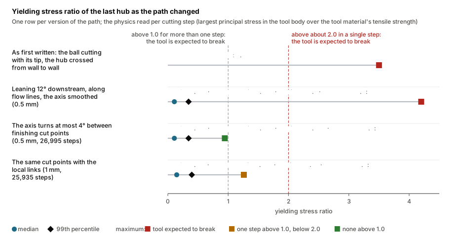
The last hub's yielding stress ratio as the path changed: one row per version of the path, the dot the median, the diamond the 99th percentile and the square the maximum. HiNC's rule expects the tool to break above 1.0 for more than one step, or above about 2.0 in a single step. Read per cutting step on HiNC 3.2.39.
The last hub's cutting steps as the path changed, read step by step on HiNC 3.2.39:
| Path of the last hub | Resolution | Cutting steps | Stress ratio: median / 99th percentile / maximum | Steps above 1.0 | Force: 99th percentile / maximum |
|---|---|---|---|---|---|
| As first written: the ball cutting with its tip, the hub crossed from wall to wall | — | — | maximum 3.5 | — | — |
| Leaning 12° downstream, along flow lines, the axis smoothed | 0.5 mm | — | 0.108 / 0.344 / 4.2 | 5 | — |
| Turning at most 4° between finishing cut points | 0.5 mm | 26,995 | 0.108 / 0.344 / 0.944 (90th percentile 0.261) | 0 | 175 / 483 N |
| The same cut points with the local links | 1 mm | 25,935 | 0.147 / 0.397 / 1.26 | 1 | 201 / 647 N |
Numbers that look alarming but are not
- Situation. Read naively, the charts showed eight times the programmed feed, chips up to 0.88 mm thick against 0.067 mm per tooth (2,400 ÷ 12,000 rpm ÷ 3 flutes), and, at 0.5 mm, infinite depth in 13 % of the hub's cutting steps.
- Risk. Rewriting a sound path to chase a readout while a real overload hides in the same chart: the first path showed such readouts (0.4–0.9 mm chips, 30–60 mm depth) with its real fault.
- How it was noticed. The numbers contradicted the path's own feeds.
- Resolution. Values are read per step, where the tool touches (Watching the Run): a chart window's maximum is dominated by rapids and plunges; at 0.5 mm the chip readout jumps in steps of 0.12 mm, reading 0.39, 0.51, 0.63 or 0.75 mm in about a quarter of the hub's cutting steps; each infinite depth is a single step between neighbours of 1–3 mm. Stress ratio and force judge the cut, and told the first path's fault apart.
- Evidence it held. Stage C's 25,935 cutting steps run at 2,400 mm/min at the median, the 99th percentile and the maximum; sampled thick-chip steps are steady cuts at 130–170 N.
Where the memory went
- Situation. One passage of an early path peaked at 24.4 GB at 0.5 mm and 88.5 GB at 0.25 mm, both in the geometry comparison, against 3.3 GB while cutting at 0.5 mm (measured on HiNC 3.2.39, and not measured again on the large part). A reload or a restart clears the run's results.
- Risk. A run that runs out of memory, peaks that include the previous run, and values that can no longer be read.
- How it was noticed. Memory logged every 30 s; one whole-job run lost its results to a reload and was played again.
- Resolution. The resolution follows the purpose, and the job can run stage by stage with the comparison last. HiNC is restarted before each measured run, and every value read in that session. The budget: about 4.6 GB per million steps, then about 10 GB for the comparison at 1 mm and 3 GB for the NC conversion (Memory Planning).
- Evidence it held. The stages peaked at 7.2, 9.1 and 12.1 GB against 23.5 GB for the whole job in one run: within 16 GB with a restart between stages, though no 16 GB computer was tried.
One passage of an early path, 135,162 steps, at three resolutions, on HiNC 3.2.39:
| Resolution | Wall time | Memory while cutting | Peak, in the comparison |
|---|---|---|---|
| 1 mm | 317 s | — | 11.8 GB, in a process that had run before |
| 0.5 mm | 504 s | 3.3 GB | 24.4 GB |
| 0.25 mm | 1,143 s | about 13 GB | 88.5 GB |
The whole part at 0.5 mm, the resolution of the pictures:
| Run | Steps | Wall time | Peak memory |
|---|---|---|---|
| Whole job on an early path, no comparison | 2,108,965 | 5,338 s | 15.4 GB |
| Resumed at B: B, C and the picture pose, on the path before the local links, no comparison | 1,422,277 | 3,651 s | 18.2 GB |
| Every stage read from its record, the picture pose played, then the whole-part comparison | 42 | 207 s | 40.4 GB |
A resumed run that silently starts over
- Situation. The staged mission must resume at stage B or C from the earlier stages' records.
- Risk. A resumed run that recuts the raw stock without a message.
- How it was noticed. Working out from HiNC's source when a record is read; unticking a whole stage skips its records too. The agent's first account of the rule was wrong; the second review round caught it.
- Resolution. A Read On First Or Write record is read only if its file exists and nothing has played yet in the run, so a resume unticks only the earlier stages' program rows; an STL stock needs a stage-0 record (A Mission That Resumes).
- Evidence it held. Resumed at B, then C, the runs ended with the whole job's part; the stage counts sum to 99 steps fewer than the whole job's.
The owner saw strange lifts
- Situation. Where the straight move between two finishing cuts was refused, the tool left the blank, rising up to 95 mm: 1,406 times to bridge a short gap, with a median lift of 55 mm.
- Risk. About 1 h 25 min of wasted simulated time, and a path no machinist would accept.
- How it was noticed. The owner picked one on HiNC's canvas, a 30 mm rise and fall to cross 10.7 mm; the agent counted the rest.
- Resolution. Local links, in finishing only: lift 1.5 mm off the surface (up to 12 mm if needed), cross in steps of 1 mm and 2°, come down at 900 mm/min, every pose checked. The first version lifted along the nearer surface's normal and failed at the owner's own spot, a wall-hub corner 3.00 and 3.01 mm away; lifting along the bisector passed.
- Evidence it held. 1,380 links became local; stage C's per-step physics is unchanged; simulated time fell from 49,139 s (13 h 39 min) to 44,002 s (12 h 13 min).
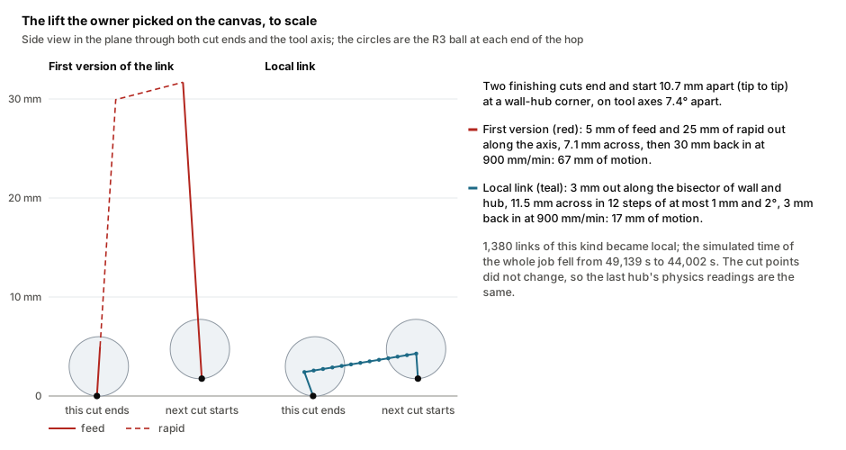
The same hop two ways, to scale in one side view through both cut ends and the tool axis (the coordinates are the case's final CL): the two finishing cuts end and start 10.7 mm apart, tip to tip, at a wall-hub corner, on tool axes 7.4° apart. The first version fed 5 mm and rapided 25 mm out along the axis, crossed 7.1 mm and fed 30 mm back in at 900 mm/min; the local link lifts 3 mm, crosses 11.5 mm in 12 steps and comes down 3 mm at 900 mm/min. The cut points did not change, so the last hub's physics readings are the same.
How the programs pass from one cut to the next after the change (the counts leave out each operation's first approach and last retract):
| Program | Straight feed move | Local link | Out to 8 mm outside the blank | Full 100 mm retract |
|---|---|---|---|---|
| Roughing, passages 1–15 | 32,685 | none: roughing never links locally | 315 | 855 |
| Walls of all 30 blades, then the hubs of passages 1–14 | 3,208 | 1,380 | 14 | 147 |
| Hub of passage 15 | 77 | 15 | 1 | 3 |
Pictures that show the part as it is
- Situation. Surfaces cut in the current run render pink, a built comparison stays on screen until the next run, and selecting a chart step does not move the machine.
- Risk. A pink part, a coloured one, or a tool parked far from the work.
- How it was noticed. The first renders.
- Resolution. The pictures come from a run that reads the stage records and plays only a short pose path re-tracing a finished wall, at 0.5 mm, on the path before the local links.
- Evidence it held. That run cut nothing in 15 s; with the comparison on it took 207 s and 40.4 GB.
Which splitter belongs to which passage
- Situation. In this data the splitter between main blade 0 and main blade 1 is splitter 1, not splitter 0: each splitter's THETA is about 12° less than that of the main blade with the same number.
- Risk. Picking the splitter by its number puts the passage's boundary on the wrong blade, and the path then runs through a blade.
- How it was noticed. From the THETA values of the sections.
- Resolution. The path script does not hard-code the splitter: passage 1 is the free run between main blade 0 and main blade 1 on the circle the ball centre follows, and the splitter inside it is whichever splitter label sits between them (here splitter 1).
- Evidence it held. Passage 1 took splitter 1; the whole job's comparison shows the passages and blade faces within ±0.1 mm, and no collision was reported.
A summary that looked like a wrongly read record
- Situation. The agent's play script printed the message summary with one text per message id, so
in the run resumed at stage B the two
ReadMeshedGeommessages both showedA-init.wct. - Risk. Believing that the resumed run read the wrong record.
- How it was noticed. Reading the run summary.
- Resolution. HiNC's source shows that each read uses the file name of its own row.
- Evidence it held. The two reads were A-init and A-done, and that run ended with the whole job's part (see the resumed-run dilemma above).
Closing the project after a restart returns 400
- Situation. After a restart HiNC has no project loaded, and
POST /api/Project/closeanswers 400No project is currently loaded. - Risk. A rebuild script that stops on this error before it has built anything.
- How it was noticed. Every measured run began with a restart and then a rebuild of the project.
- Resolution. The rebuild script tolerates this 400, deletes the old project file and builds the project anyway.
- Evidence it held. The rebuild straight after a restart ran through.
Results and benefits
All simulated: measured on HiNC 3.2.39 on a 32-core server at 1 mm, HiNC restarted before each run.
| Run | Steps | Wall time | Peak memory |
|---|---|---|---|
| Trial, passage 1: all 99,611 lines executed, one file-length note (comparison on, NC conversion off) | 153,128 | 357 s | 8.0 GB |
| Whole job, two runs (comparison and conversion on) | 2,298,853 | 4,181 and 4,145 s (70 min) | 23.5 and 22.4 GB |
| Stages A / B / C (each converting its program, only C building the comparison; B, C resumed; A from an earlier run of the same file) | 1,031,477 / 1,239,043 / 28,234 | 1,642 / 2,347 / 131 s (27 / 39 / 2 min) | 7.2 / 9.1 / 12.1 GB |
| Posted NC replayed (comparison on) | 2,299,229 | 4,073 s (68 min) | 20.7 GB (11.1 GB at the last step) |
Collision probe, a 13-line program: the ball plunged 3 mm into the rotary table at x = 240 mm, outside the 215.9 mm rim, the tool and the holder at least 18 mm from the stock; one file-length note, seven Collision--Detected errors, the table against the flutes on the way down and back up, and one Play-Touch--None warning, the stock never being touched (comparison and conversion off) |
551 | 5 s | 1.6 GB |
| Whole job | Value |
|---|---|
| Lines executed | 627,472 + 852,646 + 13,963, every line |
| Stock touched, comparison built | both: IsTouched peaks at 1, and the comparison overlay is built |
| Simulated time | 44,001.72 s (12 h 13 min) |
| Messages | three file-length notes; no collision, rapid through material or stroke limit |
| Geometry comparison | passages and blade faces within ±0.1 mm |
| Last hub with physics, 25,935 cutting steps | feed 2,400 mm/min throughout; force median 75 N, 99th percentile 201 N, maximum 647 N; stress ratio median 0.147, 99th percentile 0.397, maximum 1.26 in one step (0.94 at 0.5 mm) |
Posted G43.4 NC |
621,853 + 848,924 + 13,911 lines, every line executed; 376 steps more than the CL play; only its three file-length notes |
For a machining engineer. An agent can write a five-axis impeller path of demonstration quality, and HiNC's checks found real faults in it before any machine was involved: rapids starting in contact, and a path predicted to break the tool. It is not proven for production: one hub finish was load-checked, in aluminium.
For a teacher or student. Units checked against a known dimension; a tapered ball's diameter; why a ball end mill should not cut with its zero-speed tip, and why a swinging axis overloads the upper flank; why a readout quantised by the resolution is not a load.
For someone weighing the approach.
- Supplied by people: the task, the owner's rulings and one observation.
- Delivered: a path for all 15 passages, clean on HiNC's checks, and a
G43.4program that replays every line; the stress-ratio peak brought from 3.5 to 0.94; a tenth of the simulated time saved. - Cost: about 1,400 lines of Python, some 840 for the tool path, which generates in about 5 minutes; 70 min and 23.5 GB per whole-job run, or stages of at most 12.1 GB; 68 min for the NC replay; one run repeated after a reload.
- Relied on: review agents.
- Cannot tell: how the path cuts metal, or titanium.
Honest limits
- Demonstration quality. The path is the agent's own CAM, never tried in metal.
- Load-checked. Only the last hub, 28,284 of 2,298,853 steps. Every passage is the same path turned by 24° and every hub follows all walls, so it stands for the other hubs, not for roughing, where the tool is most engaged, or for the walls. The loads assume AA7075 and the agent's tool.
- The holder's clearance is the agent's own check. The generator keeps the taper, shank and holder 1 mm from the blades and the hub at sampled heights (2–20 mm apart up the tool) and does not compare the depth along a steeply tilted axis with the flute; the run's clean collision messages are not offered as more than that.
- A simpler part. Invented nose, disc and bore; tips trimmed to the shroud line (by up to 0.34 mm) without the tip clearance; no fillet; the hot shape, possibly mirrored, since THETA's direction is unstated; a generic machine; no clamping.
- Simulated time is the tip's path over the feed, capped by the 36,000°/min rotary rapid rate, plus 20,000 mm/min rapids, with no acceleration: not a cycle time.
- The posted NC was judged by its counts, messages and own comparison, not number for number against the CL play; its 376 extra steps were not traced.
- Measured on one build. The run times, memory peaks and the geometry comparison come from HiNC 3.2.39 only.
- The pictures predate the local links (same cut points). No blind build was made.
What a reader can take to their own case
- Confirm the units against a known dimension first.
- Read back the tool HiNC built and compare it with the one intended.
- Prove the pipeline on a small case, and one section before the whole job (Cutter-Location Playback).
- Put physics where it stands for the rest, read it per step, and say what it does not cover (Watching the Run).
- Prove a safety check with a deliberate collision before trusting its silence.
- Stage long jobs, and budget the comparison like a run of its own (Memory Planning, Geometry Validation).
- Read every value before anything reloads the project.
- Watch the canvas: a motion that looks strange usually is.
Source and licence
Source. G. Medic, O. P. Sharma, J. Joo, L. W. Hardin, D. C. McCormick, W. T. Cousins, E. A. Lurie, A. Shabbir, B. M. Holley and P. R. Van Slooten (United Technologies Research Center), High Efficiency Centrifugal Compressor for Rotorcraft Applications, NASA/CR-2014-218114/REV1, NASA Glenn Research Center, 2017 — https://ntrs.nasa.gov/citations/20180001471; its supplement, with
AppendixE.4_HotCoordinates/— https://ntrs.nasa.gov/citations/20180001472. If the links move, search forHigh Efficiency Centrifugal Compressor for Rotorcraft ApplicationsorNASA/CR-2014-218114. Use REV1 (2017), not the superseded 2014 original.Licence and terms. The NASA Technical Reports Server record's copyright determination is Public Use Permitted; it attaches no licence, names no rights holder and marks the work as not a U.S. Government work, so the data are not public domain. The use here rests on reading the determination as covering the coordinates, not on legal advice. NASA's terms of use for its scientific and technical information apply. The data folder states that it is “not subject to the EAR or the ITAR”.
Attribution.
Impeller geometry from NASA/CR-2014-218114/REV1, “High Efficiency Centrifugal Compressor for Rotorcraft Applications”, G. Medic et al., United Technologies Research Center, for NASA Glenn Research Center; supplement https://ntrs.nasa.gov/citations/20180001472 (Appendix E.4 hot coordinates; NTRS copyright determination: Public Use Permitted). Tech Coordinate lofted the surfaces and made the blank, tool path, tool, holder and machine set-up; NASA does not endorse Tech Coordinate, HiNC or this case.
Under NASA's terms the data are provided as is, without warranty. No NASA logo is used.
What was changed. The 25 files are used byte for byte; everything else is the agent's, as the set-up table records. Only numbers come from the report.
Backup. This page offers no download. The company site keeps a backup of the 25 files in case the links stop working, and removes it at the rights holder's request.
A file fetched from the supplement can be checked against the one used here by its SHA-256, as the source notes give it (the files as NASA serves them, CRLF line ends included):
| File | What it is | SHA-256 |
|---|---|---|
README_ExportControlClassification.txt |
export-control statement (quoted under Licence and terms) | 0767de94b01705294ab73f52de876d66954fe4145690feecc90440271a015a27 |
table_C_1_flowpath_hub.txt |
hub line, 350 points, columns x r |
21de8671e5dd649986a182499d0cce45e3e4e12347594a7275fdb0930cd3a3e5 |
table_C_2_flowpath_shroud.txt |
shroud line, 310 points, columns x r |
252e39b26c151929ed4fcc778487eef404c154aa32e4d08cea5a2af03fed909e |
table_C_3_impeller_main_blade_section_1.txt |
main blade, section 1 (hub) | bc0ebeec00a0a0d8a8d68dc668b5fed9f8ca01ce89b5388c9dfb04d0bf57e68d |
table_C_4_impeller_main_blade_section_2.txt |
main blade, section 2 | 50d33e8f687217ba8024faba7b6fda39e0cde87a1a72369fa5e8263795434ce4 |
table_C_5_impeller_main_blade_section_3.txt |
main blade, section 3 | f8d1f6759c719110ac5591db0bf13ec7d2c93af4b255f5d784f371780e471707 |
table_C_6_impeller_main_blade_section_4.txt |
main blade, section 4 | 4fadf10126118f579173a95314bc9914e41e0351c2035cd955721b35774fd1bc |
table_C_7_impeller_main_blade_section_5.txt |
main blade, section 5 | 7770b1e37704db91e698a91b13edbb3b68b89356b4734a4de313e4ecedbdeeed |
table_C_8_impeller_main_blade_section_6.txt |
main blade, section 6 | 8b1baf77991b7f6b17fe82796333c996cd5d69ec007b999ffcfb8779530b4510 |
table_C_9_impeller_main_blade_section_7.txt |
main blade, section 7 (no header row in the source) | 203a8ac02d2c03765079767c78fc449c70a49a203fecd73a3dc88f11704d35a0 |
table_C_10_impeller_main_blade_section_8.txt |
main blade, section 8 | 4b147950463587c35bdface9b20c645aa10c46402c8407f7672a46ef9f691491 |
table_C_11_impeller_main_blade_section_9.txt |
main blade, section 9 | dad49d72a4e353df41238fe228bd9650d56c6ac3e91b20003ce429660511ece5 |
table_C_12_impeller_main_blade_section_10.txt |
main blade, section 10 | 62e8d39e0bae6162083b59bf4b51b50f8df7db3c487daf327dc473f0ab45e2ef |
table_C_13_impeller_main_blade_section_11.txt |
main blade, section 11 (shroud) | 264b520bb549e0a61176b95c7cc0f9a74014960896e2b0d507d3a48ffd283b61 |
table_C_14_impeller_splitter_blade_section_1.txt |
splitter blade, section 1 (hub) | 50e935d4dd8fea75b061a99fd97a1977fa067da8a4b4d214c3018b1611612412 |
table_C_15_impeller_splitter_blade_section_2.txt |
splitter blade, section 2 | 3bc2962aa35758d990898262b062590b05d1d4d91a678ce0ddb0a0cbd8acbd4e |
table_C_16_impeller_splitter_blade_section_3.txt |
splitter blade, section 3 | 13470e3abff314281bd67df78d586f73258cf6d00b789d5bec93dce3441ed1b4 |
table_C_17_impeller_splitter_blade_section_4.txt |
splitter blade, section 4 | 076b0635d13e2a59f5cfbfcc92e5fe3c8ffcb9e25721f04785239b929c88dcfd |
table_C_18_impeller_splitter_blade_section_5.txt |
splitter blade, section 5 | d81afb3c67126c932583f0b763874657c52b185346336a0f4f25de283d512912 |
table_C_19_impeller_splitter_blade_section_6.txt |
splitter blade, section 6 | 7afa5b38d0fa05edf1584d9c8937d3422160219abfff86ad50c7f3b72a675444 |
table_C_20_impeller_splitter_blade_section_7.txt |
splitter blade, section 7 | d74d1288f053b0a34b143bc08135240473a1e9156dc2614167a190d1c1251591 |
table_C_21_impeller_splitter_blade_section_8.txt |
splitter blade, section 8 | ec05dd5f59f15f4d596a7e07c32780d55f77b1a209f85daab0ea52124876986e |
table_C_22_impeller_splitter_blade_section_9.txt |
splitter blade, section 9 | 73ffa548204fc027b55b3c7414187d48dde4f489a60e0f83f6286c60a82e6c12 |
table_C_23_impeller_splitter_blade_section_10.txt |
splitter blade, section 10 | 4ca4b956137cb7a8835e300d77b3784ea92d45f2b84dad7925c1c32b5df8be50 |
table_C_24_impeller_splitter_blade_section_11.txt |
splitter blade, section 11 (shroud) | 3f12174fa42f80dac07eaf45f9e5a43abc09326852d47c6727aa5aff503171cd |
The same folder also holds the diffuser and exit-guide-vane sections (table_C_25 to table_C_30)
and AppendixC.pdf; the impeller does not need them, and they are not used here.