NIST five-axis test artifacts: cone frustum and truncated square pyramid
- Original source
- S. Moylan, D. Blumenfeld, M. McGlauflin, R. Fesperman, M. A. Donmez (NIST and Pennsylvania College of Technology), Evaluation of Proposed Test Artifacts for Five-Axis Machine Tools, ASPE 2011 Annual Meeting — tsapps.nist.gov, publication 909384
- Search keywords
Evaluation of proposed test artifacts for five-axis machine tools,NIST cone frustum truncated square pyramid five-axis- Licence
- Official contribution of the National Institute of Standards and Technology (NIST); not subject to copyright in the United States (the paper's own footnote; see NIST's copyright statement).
- Attribution
-
Artifact dimensions and cutting conditions after Moylan et al., National Institute of Standards and
Technology (NIST), ASPE 2011. NIST does not endorse this case, HiNC, or any product used here.
Of the paper, only its Figure 1, the two drawings, is reproduced here; the models, the cutter-location
files and the generic five-axis machine were made by Tech Coordinate from the paper's drawings, as the
story below and the zip's
SOURCE.mddescribe. - About the case
- Two parts proposed for testing five-axis machine tools, finish-machined with the side of a Ø12.7 mm end mill while all five axes move: a Ø200 mm cone frustum tilted 10° and a 125 mm truncated square pyramid tilted 20°. The paper gives two drawings and the cutting conditions, but no model, no toolpath, no program and no machine model.
The story
An AI agent was given the paper and HiNC running as a web service, to be driven only through its web
API and its public documentation. Missing: the models, the stock, the fixture, the toolpath, the
program, the holder, the alloy and the machine, and no open-source CAM computes simultaneous
five-axis toolpaths. The agent drew both parts and wrote the cutter locations itself in a short
Python script: the side of the cutter along the cone's slant line, and on the pyramid the tool axis
through the pyramid's axis on every face. HiNC then solved the axes of a generic B/C five-axis
machine, checked it for collisions and wrote the Fanuc G43.4 program. The agent played
the toolpath two independent ways, on HiNC's machine-independent cutter-location device and on the
machine, replayed the program HiNC wrote, and accepted a result only when they agreed; a second agent,
given only the written instructions and a copy of the case files, then rebuilt the pyramid.
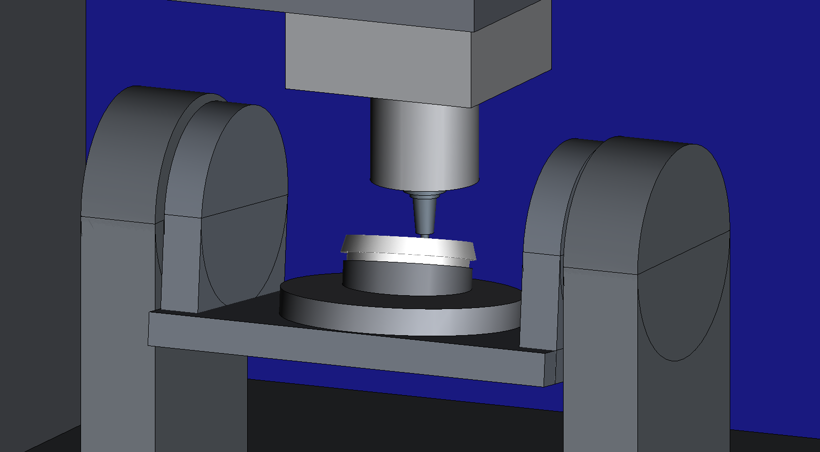
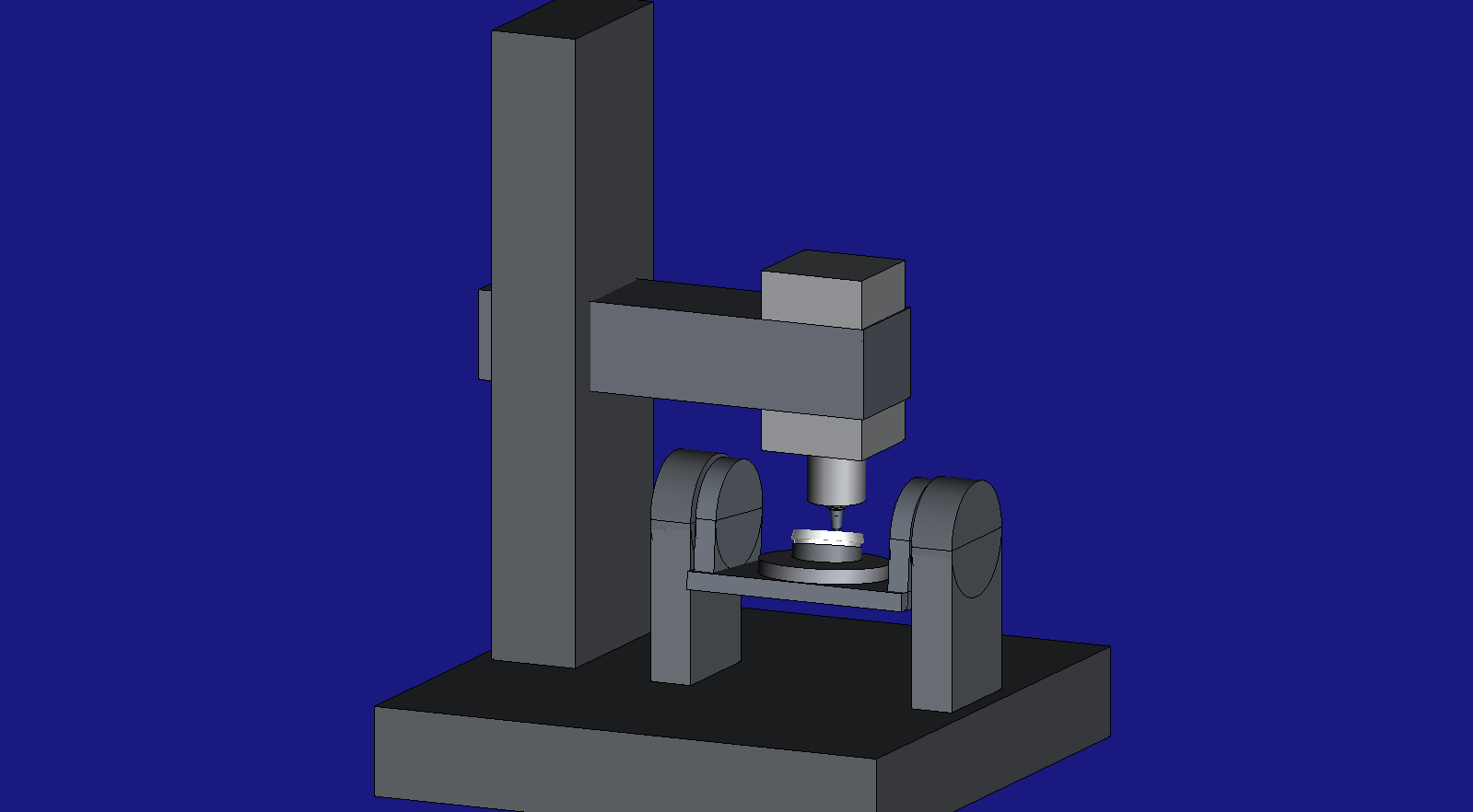
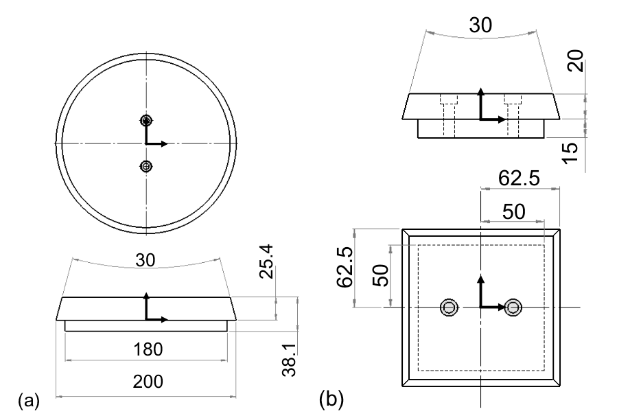
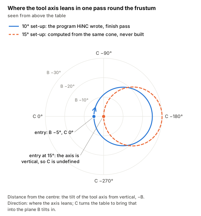
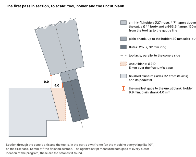
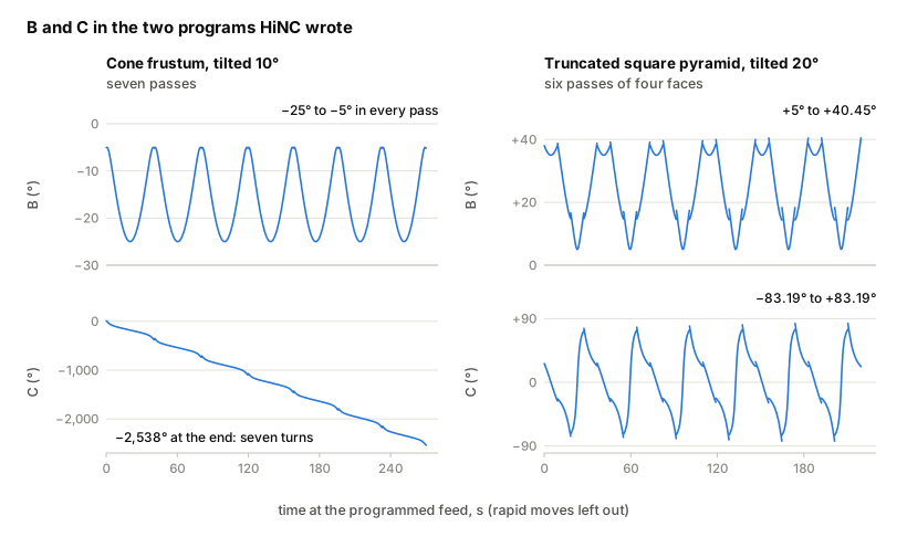
The two renders are HiNC's, from models the agent drew after the drawings of Moylan et al. (NIST). The drawings are the paper's Figure 1; the section and the two charts are drawn from the agent's own geometry and the programs HiNC wrote.
Four of its fourteen dilemmas
Half-widths or full widths?
The pyramid's drawing carries 62.5 and 50 without saying which dimension they are. Measured at eight times magnification, they share one scale with the heights, and their dimension lines start on the centre line: they are half-widths, so the pyramid is 125 mm square. The drawn top square and the paper's own measurement plot, 110 mm along a face, agree.
Tilt 10° or 15°?
The paper tests the frustum at both. On a B/C table, 15° of tilt plus the cone's 15° half-angle makes the tool axis exactly vertical at the entry point, where the C axis is undefined and can swing half a turn. The agent chose 10°: the program HiNC wrote keeps B between −25° and −5° and winds C steadily, with no half-turn anywhere.
3,436 collisions between the cradle and the head
The first play on the machine reported the spindle head hitting the tilting cradle. It looked like a toolpath problem. The agent computed the machine's pose at every cutter location with its own kinematic model instead, found the same span of the toolpath, and saw why: the spindle nose reaches into the cradle's side wall. The agent that built the machine for another case widened the cradle; no replay collided afterwards.
Should program zero tilt with the part?
The part sits tilted, and program zero could tilt with it. But HiNC's machine play uses program zero's full position and orientation, while a replayed NC program uses only the work offset's translation, so a tilted program zero would make the two cut in different places without a message. The agent read how HiNC places a cutter location on the machine before building the project, built the tilt into the models and the toolpath, and kept program zero parallel to the table. The machine play and the program replay agree in cutting-depth peak to 0.00001 mm.
The other ten, among them a work offset read too early, a home position inside the part, and a server that crashed when the picture was taken, are in the full record.
The result
HiNC reached every cutter location on the machine, and both written programs replayed with every line executed and no warning or error: 36,981 and 29,786 steps on the machine for the frustum and the pyramid, about 272 and 226 s of simulated machining, and the same cutting-depth peak in the machine play and the program replay to 0.00001 mm. By the agent's own geometric check the holder stayed 9.9 and 11.7 mm clear of the uncut blank. A play took 5 to 35 s at 1 mm and 140 to 290 s at 0.25 mm on a 32-thread server; the heaviest raised the server's memory by about 1.7 GiB. Everything is simulated; no part was cut on a real machine.
| Key number | What it is |
|---|---|
| 125 mm | the pyramid's base: the drawing's 62.5 runs from the centre line, so it is a half-width |
| 5° to 25° | the frustum's tool axis from vertical at the chosen 10° of tilt; at 15° it would reach 0° at the entry, where C is undefined |
| 3,436 → 0 | collisions between the cradle and the spindle head: the first play on the machine, then every replay after the cradle was widened |
| 36,981 / 29,786 | steps of the toolpath on the machine, frustum / pyramid; the written programs replayed in 37,020 / 29,642 steps, every line executed, with no warning or error |
| 0.00001 mm | how closely the machine play and the replay of the program HiNC wrote agree in cutting-depth peak |
| B −25° to −5° | the frustum's B in the program HiNC wrote, while C winds seven turns; the pyramid's stay within B +5° to +40.45° and C −83.19° to +83.19° |
| 9.9 / 4.0 mm | the frustum's holder and plain shank above the uncut blank, the smallest gaps the agent's own check found (11.7 / 7.3 mm on the pyramid) |
| 140 to 290 s | a 0.25 mm play on a 32-thread server; the heaviest raised the server's memory by about 1.7 GiB |
What it brought
- For a machining engineer: five-axis side milling of analytic surfaces without a
five-axis CAM. The agent writes the cutter locations, HiNC writes the
G43.4program, and before any metal is cut the simulation caught a cradle too narrow for the head; the work offset HiNC read back, set against the one worked out from the set-up, showed when it must be read; and the agent, reading the machine's home against the tool length, caught a home position that would have driven the tool into the part. - For a teacher or a student: reading a drawing that carries bare numbers, a real kinematic singularity and how the choice of tilt avoids it, and why a clean message list is not proof while two independent paths are.
- For someone deciding whether to use an agent with HiNC: fourteen dilemmas found and resolved; a second agent given only the written instructions and a copy of the case files rebuilt the pyramid, and the program HiNC wrote in its build matched the first one byte for byte. People supplied the server, the rules (one folder per case, the team's own set-up files kept apart from the source's) and the redeploys; the agent did the rest.
Read the full case record: NIST five-axis test artifacts
The paper and its backup
| Case | Setups | Original files | Backup of the originals |
|---|---|---|---|
| NIST 5-axis | Cone frustum tilted 10°; truncated square pyramid tilted 20° | the paper (PDF) | Showcase-NIST-5axis-ConeFrustum.zip |
The zip holds the paper as NIST serves it, with the models, cutter-location
files and generic machine the agent made from it under Setup/, and its written instruction.