NASA HECC centrifugal impeller (5-axis)
- Original source
-
G. Medic, O. P. Sharma, J. Joo, L. W. Hardin, D. C. McCormick, W. T. Cousins, E. A. Lurie, A. Shabbir,
B. M. Holley, P. R. Van Slooten (United Technologies Research Center),
High Efficiency Centrifugal Compressor for Rotorcraft Applications, NASA/CR-2014-218114/REV1,
NASA Glenn Research Center, 2017 — report
ntrs.nasa.gov/citations/20180001471;
coordinate data in the supplement
ntrs.nasa.gov/citations/20180001472
(a 4.93 GB zip; the case uses 25 files of its folder
AppendixE.4_HotCoordinates/: the impeller tables C.1–C.24 and the export-control README) - Search keywords
High Efficiency Centrifugal Compressor for Rotorcraft Applications,NASA/CR-2014-218114,NTRS 20180001472,HECC impeller hot coordinates- Licence
- NASA Technical Reports Server copyright determination: Public Use Permitted. The record attaches no licence, names no copyright owner and marks the work as not a U.S. Government work, so the data are not public domain; NASA's terms of use for its scientific and technical information apply, and the data come as is, without warranty. This site's backup rests on reading the determination as covering the coordinates and is removed at the rights holder's request. The data folder states that it is not subject to the EAR or the ITAR.
- Attribution
-
Impeller geometry from NASA/CR-2014-218114/REV1, "High Efficiency Centrifugal Compressor for Rotorcraft
Applications", G. Medic et al., United Technologies Research Center, for NASA Glenn Research Center;
supplement https://ntrs.nasa.gov/citations/20180001472 (Appendix E.4 hot coordinates; NTRS copyright
determination: Public Use Permitted). Tech Coordinate lofted the surfaces and made the blank, tool path,
tool, holder and machine set-up; NASA does not endorse Tech Coordinate, HiNC or this case.
Everything derived or chosen is listed in the zip'sSOURCE.md. - About the case
- A centrifugal compressor impeller designed for rotorcraft, 431.8 mm across the blade tips,
with 15 main blades and 15 splitters. The data folder gives a hub line and a shroud (casing) line as
x rpairs and eleven sections of each blade shape asX, R*THETA, Rtriples, with no unit and in the running (hot) shape; the shape for manufacture is not supplied. The report gives no solid model, blank, program or machine.
The story
An AI agent worked from those coordinate files and HiNC running as a web service, to be driven only
through its web API and its public documentation. Missing: the unit, a solid model, the blank, the
fixture, the machine, the tool, the holder and any tool path, and HiNC has no CAM. So the agent acted as
the CAM programmer: its Python scripts lofted the part, made a turned blank and a generic five-axis
machine, and wrote the five-axis cutter locations. HiNC played them with a tapered ball end mill in a
shrink-fit holder, checked them, computed the cutting load, compared the result with the design and
posted it as Fanuc G43.4 NC, which the agent replayed. The agent proved the chain on a small
cone-frustum test and on one of the 15 passages between the blades before running the whole job in three
resumable stages; reviewer agents, in later rounds each paired with one told to refute it, checked its
tool path and its written notes.
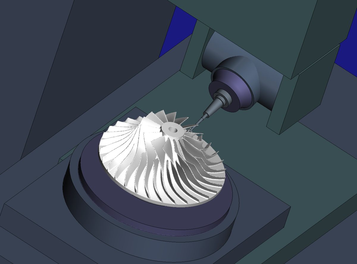
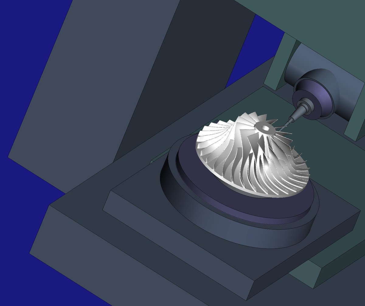
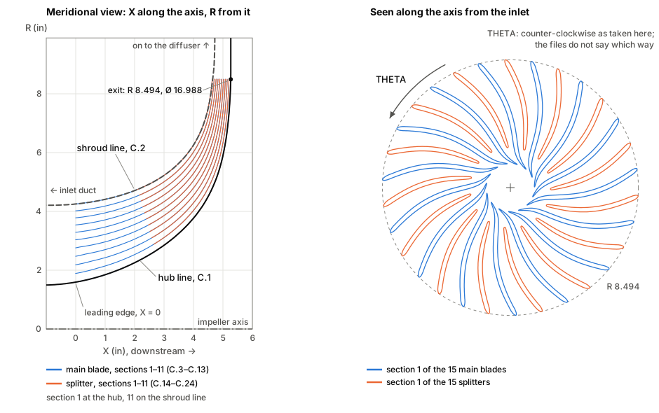
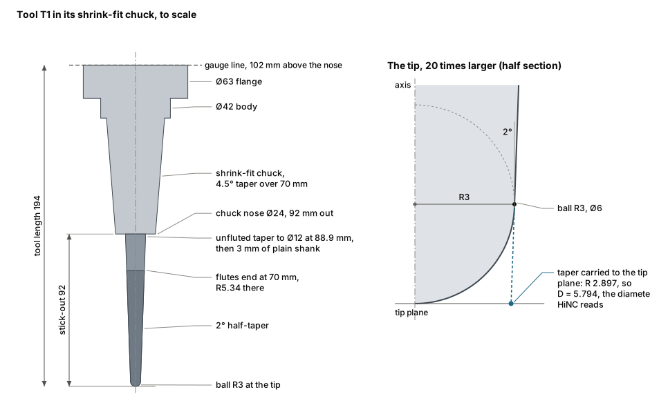
Pictures rendered by HiNC from a model the agent lofted through the blade coordinates of NASA/CR-2014-218114/REV1 (G. Medic et al., United Technologies Research Center, for NASA Glenn Research Center). The plot draws those coordinates as published; the tool drawing shows the agent's tool and holder to scale; the two charts are drawn from the run's per-step readings and from the final path.
Four of its seventeen dilemmas
The coordinates have no unit
No file names a unit; the exit radius reads 8.49376. Taken as millimetres, the part would be 25.4 times too small. The agent doubled three radii and compared them with the report's Table 2: 3.190, 5.315 and 16.988, the table's diameters in inches to the last digit. The part is used at 1:1 in inches, 431.8 mm across the tips.
Retracts that grazed the part, entries that fed too fast
HiNC reported Play-RapidCut--Detected at the start of each
retract: the tool still touched about 0.00001 mm³ as the rapid began, and a real rapid through
the part could hide among them. A review also found entries feeding their last 3 mm, 2.5 mm in
material, at the 1,800 mm/min cutting feed. The agent made each retract feed its first 5 mm
along the axis before rising, or go out the full 100 mm when the hop is not clear outside the
blank, is longer than 80 mm or turns the axis over 10°, and fed entries in at 900 mm/min. The
whole job raised no rapid-cut message.
HiNC's physics predicted a broken tool
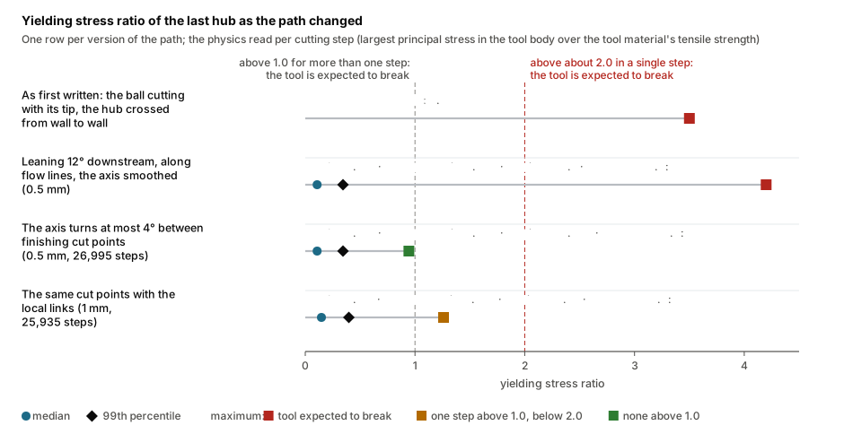
With physics on for the last hub finish, the tool's stress ratio (its stress over its material's strength) peaked at 3.5: by HiNC's rule, a broken tool. The ball was cutting with its zero-speed tip, and near the walls the axis swung 15–20° within 0.4 mm, dragging the flank 30–60 mm up through the material. The agent leaned the tool 12° downstream, recut the hub along flow lines and capped the axis turn at 4° between finishing cut points: the peak fell to 0.944 at 0.5 mm.
The owner saw strange lifts
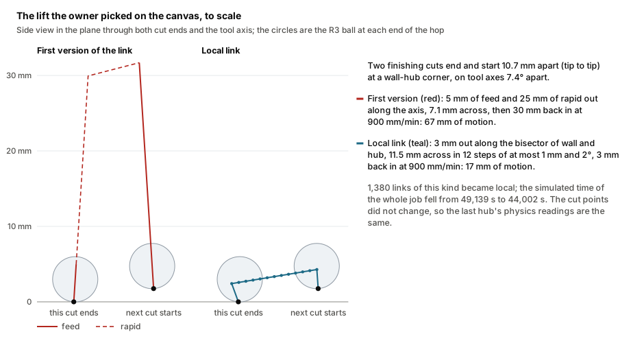
HiNC's product owner picked one move on the 3D view: the tool rose 30 mm and came down again to cross 10.7 mm. The agent found 1,406 such lifts in finishing and turned 1,380 into local links: lift 1.5 mm off the surface, cross in small checked steps, come down at 900 mm/min. The first version failed at the owner's own spot, a wall-hub corner, until it lifted along the bisector. Simulated time fell from 13 h 39 min to 12 h 13 min.
The other thirteen, among them a 4.93 GB download cut to about 5 MB by reading only the bytes needed, a design model that was not closed, and a resumed run that could silently recut the raw stock, are in the full record.
The result
The whole job, 2,298,853 steps over all 15 passages, played with every line executed and no collision,
rapid through material or stroke-limit message (the holder's clearance from the blades rests on the
agent's own sampled check); the passages and blade faces came within ±0.1 mm of the
design, in 12 h 13 min of simulated machining. On the last hub, run with physics, the feed held
2,400 mm/min and the stress ratio stayed short of HiNC's breakage rule, at most 1.26 in a single step
(0.94 at 0.5 mm). The posted G43.4 NC replayed every line. On a 32-core server at 1 mm
the whole job took 70 minutes and up to 23.5 GB of memory, or three
stages of at most 12.1 GB each. Everything is simulated; no part was cut on a
real machine.
| Key number | What it is |
|---|---|
| 2,298,853 steps | the whole job, all 15 passages: every line executed, no collision, rapid through material or stroke-limit message; the holder's clearance from the blades rests on the agent's own sampled check |
| ±0.1 mm | the passages and blade faces against the design |
| 3.5 → 0.944 | the tool's stress-ratio peak on the last hub, as first written and after the rework (at 0.5 mm); by HiNC's rule a tool is expected to break above 1.0 for more than one step, or above about 2.0 in one |
| 303 → 23 | tool-axis jumps over 6° in the hub finishing, before and after it ran along flow lines with a smoothed axis |
| 1,380 | lifts out of the blank turned into local links |
| 13 h 39 min → 12 h 13 min | simulated machining before and after those links (the tip's path over the feed, not a cycle time) |
| 70 min, 23.5 GB | the whole job at 1 mm on a 32-core server; in three stages, at most 12.1 GB each |
| 25,935 | cutting steps on the last hub, every one at 2,400 mm/min, force at most 647 N |
| 194 mm | the tool's length: 92 mm out of a shrink-fit chuck with a 102 mm gauge length |
What it brought
- For a machining engineer: an agent can write a five-axis impeller path of demonstration quality, and HiNC's checks found real faults in it before any machine was involved: rapids starting in contact with the part, and a path predicted to break the tool. It is not yet a production path: one hub finish was load-checked, in aluminium.
- For a teacher or a student: checking units against a known dimension; how a tapered ball end mill's diameter is defined; why a ball should not cut with its zero-speed tip, and why a swinging tool axis overloads the upper flank; why a readout that jumps with the resolution is not a load.
- For someone deciding whether to use an agent with HiNC: seventeen dilemmas found and resolved and all 48 review findings addressed, but no peer agent rebuilt the case blind. People set the rules (a realistic holder at the shortest stick-out that is enough, no client data or unlicensed assets, public documentation only) and pointed out one strange motion; the agent did the rest, with about 1,400 lines of Python and 70 minutes of server time per whole-job run.
Read the full case record: NASA HECC impeller
The coordinates and their backup
| Case | Original files | Backup of the originals |
|---|---|---|
| Impeller, 15 + 15 blades | NTRS 20180001472
(supplement zip, AppendixE.4_HotCoordinates/) |
Showcase-NASA-HECC-Impeller.zip |
The zip holds the 25 original files as NASA serves them, under Source/,
with the agent's scripts that build the model, the blank, the generic machine and the tool path under
Setup/, and its written instruction.