Mars rover wheel: a 0.75 mm skin between chevron grousers (4-axis)
- Original sources
- Numbers only, no model: A. Rankin et al. (Jet Propulsion Laboratory), Assessing Mars Curiosity Rover Wheel Damage, IEEE Aerospace Conference 2022 (PDF on JPL's site); E. Lakdawalla, Curiosity wheel damage: The problem and solutions, The Planetary Society, 2014 (planetary.org); photographs of the real wheels on NASA's page Curiosity's and Perseverance's Wheels.
- Search keywords
Curiosity's and Perseverance's Wheels,Rankin 2022 Mars rover wheel wear,Curiosity wheel damage Planetary Society- Licence
- Only facts (dimensions and counts) are taken from the sources. The wheel shown here is a model Tech Coordinate's agent built from those numbers; NASA's illustration is not reproduced, since NASA imagery is not in the public domain and may be used only editorially outside promotion.
- Attribution
- Wheel numbers: NASA/JPL-Caltech, The Planetary Society. Rebuilt for machining simulation by Tech Coordinate's agent; not a NASA or JPL design file and not endorsed by NASA.
- About the case
- Curiosity's wheels were machined from single blocks of aluminium: 500 mm across the treads, 400 mm wide, 19 chevron treads (grousers) 7.5 mm high, and between them a skin of 0.75 mm, "the absolute minimum thickness that was machinable".
The story
No licence-clean CAD model of the wheel exists, so an AI agent built one from the published numbers, reading the chevron shape off a photograph as numbers rather than tracing a drawing. It generated a four-axis machine with an A rotary table and a tailstock, wrote the roughing and finishing programs for one tread pitch across the full width, and drove HiNC through its web API. The cutter stays on a wheel radius while the table turns: with the table indexed and the tool moving flat, the floor of a 59 mm groove would be a chord 1.8 mm off the circle, 2.4 times the skin. The agent wrote its pass criteria down before the first play and ran a trimmed program before the whole groove.
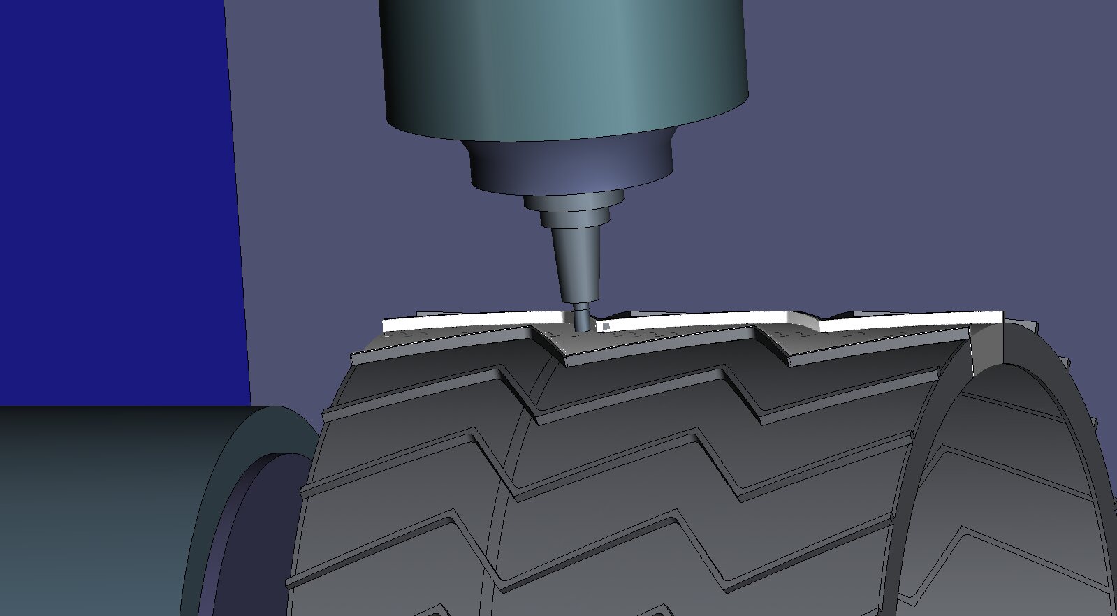
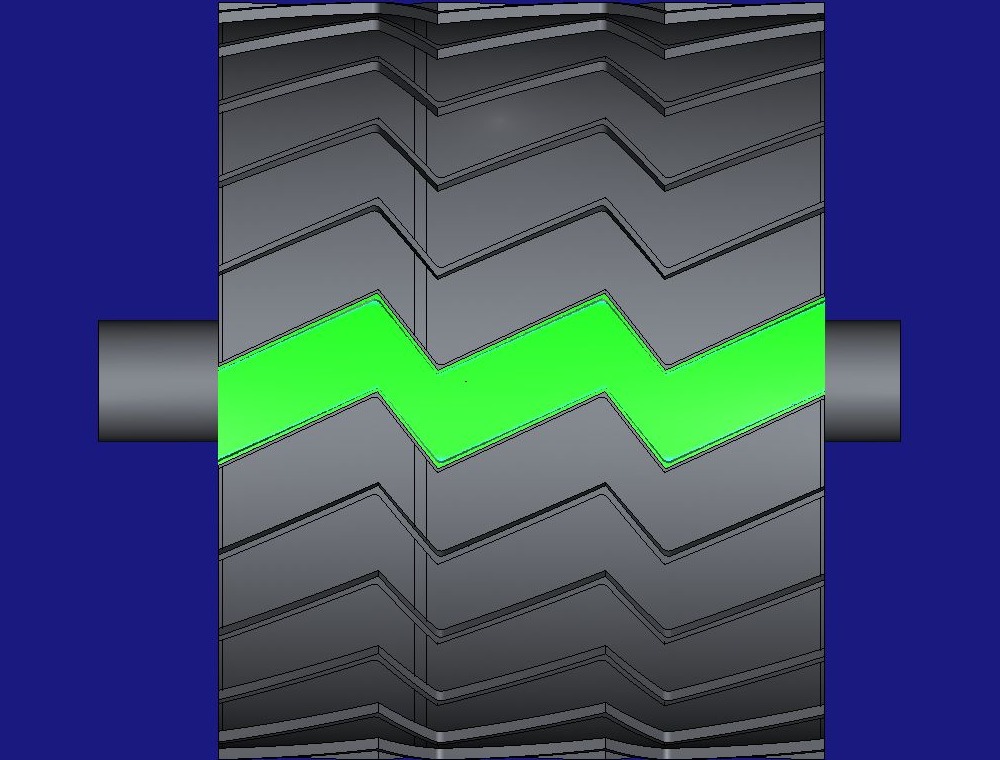
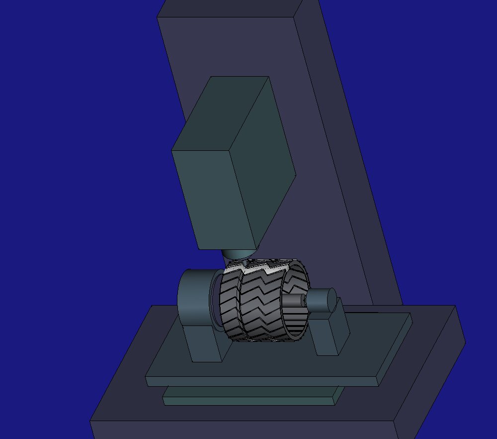
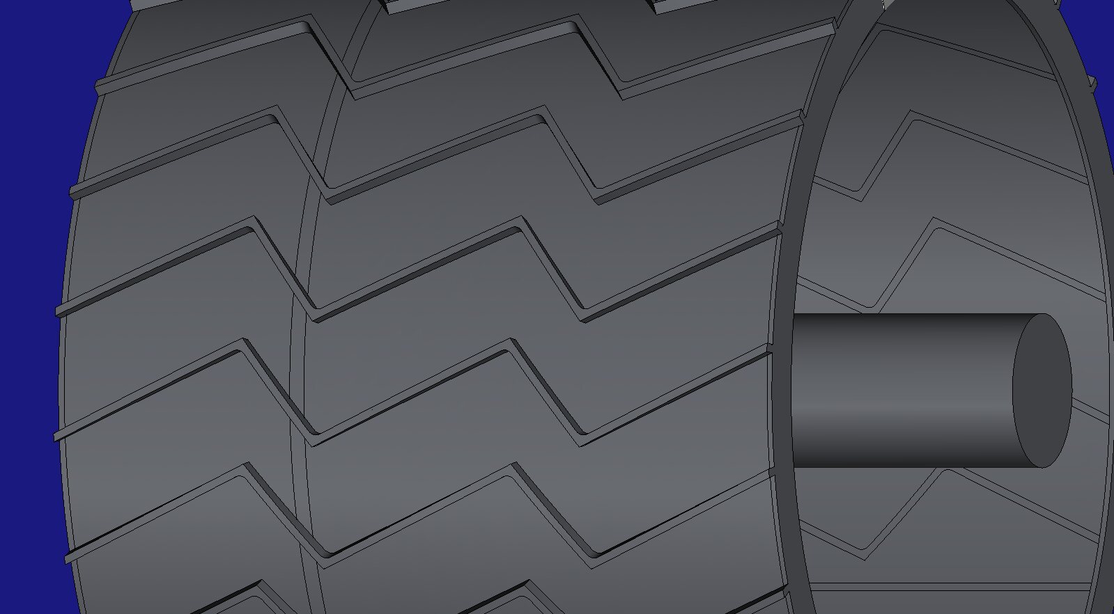
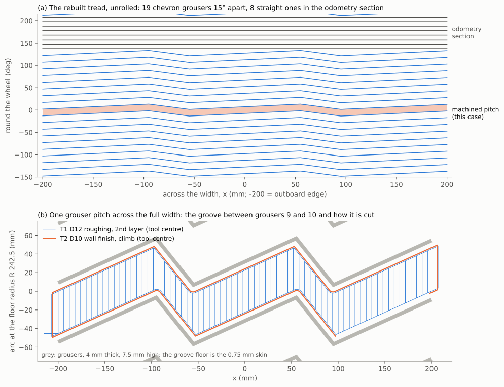
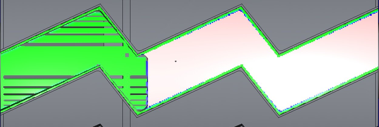
HiNC's pictures are rendered from the wheel model Tech Coordinate's agent built from published numbers; the unrolled tread is drawn by the agent's own scripts from that model and its programs. None is a NASA or JPL design file.
Four of its ten dilemmas
A grid coarser than the skin
HiNC's workpiece is a grid of cubes, and the skin is 0.75 mm. On a trimmed program the agent measured the finished part along radial lines: at 1 mm, 18 % of the lines found no skin at all, which a comparison reads as holes; at 0.25 mm every line found 0.750–0.767 mm. The acceptance ran at 0.125 mm, six cubes through the skin.
The roughing over the spindle's limit
On the trimmed program, with HiNC's AA7075 cutting data, the roughing peaked at 1.12 of the spindle's short-term power. The agent traced the steps over the limit to three kinds of move where the Ø12 cutter ran a full slot: the entry from the open edge, the step-overs along the walls, and the ends of passes on the steep chevron segments, where the walls shift 7.5 mm round the wheel for each 6 mm step. Slowing only those moves to 60 % brought the whole groove under the limit.
A feed the controller reads another way
A Fanuc control takes a block that turns the A axis as a composite distance in millimetres and degrees. Written with the tool-tip feed, a pass round the wheel would run about four times too slow at this radius. The agent scaled every block's F so that the tip moves at the intended feed, and HiNC read the roughing tip feed back at 2,880 mm/min.
The rims face inwards
The plan expected a rim standing proud of the tread on each edge for the holder to clear. The photograph shows the grousers' ends as teeth on the wheel's side, which a raised rim would hide, so the rims were built as walls running inward and the grooves open at both edges; the holder was checked against what is there: the rims, the neighbouring grousers, the mandrel, the rotary table and the tailstock.
The other six, among them three published diameters for one wheel, a flat three-axis floor that would have left 1.8 mm or broken through, walls that a radial cutter leaves 0.15 mm off a radial plane, and a skin that the cutter pulls outwards rather than presses, are in the full record.
The result
Both programs ran every line with no collision, and the comparison read the whole groove within ±0.1 mm of the design; on the finished part, 5,344 radial lines through the floor found the skin at 0.750–0.759 mm and no hole. With the shipped AA7075 cutting data the roughing as planned reached 1.08 times the spindle's short-term power; slowing only its full-slot moves brought the peak to 0.84 for 5 % more time. One groove takes 5 min 33 s of cutting, the 27 grooves of the wheel about 2.2 h; the whole groove took 19 minutes to simulate on a 32-core server. Everything is simulated; no wheel was cut on a real machine.
| Key number | What it is |
|---|---|
| 0.750–0.759 mm | the skin on the finished part, read along 5,229 radial lines; designed 0.75 mm, and no hole in 5,344 lines |
| 18 % | radial lines that found no skin at a 1 mm grid on the trimmed program; none at 0.25 mm and 0.125 mm |
| 1.08 → 0.84 | the roughing's highest spindle power ratio, as planned → with only the full-slot moves at 60 % feed |
| 183 N | median force along the cutter in the roughing, pulling the skin outwards; 24 N in the floor finish |
| 5 min 16 s → 5 min 33 s | simulated cutting time of one groove, as planned → revised (+5.3 %) |
| about 2.2 h | milling all 27 grooves of the wheel, scaled by floor area (23.9 times this groove), without indexing or tool changes |
| 98.4 % | the share of a Ø500 × 400 block cut away to leave the wheel, from the agent's model |
| 14 and 19 min | the two whole-groove runs on a 32-core server, the comparison and the export included |
What it brought
- For a machining engineer: HiNC showed before any cut that the thin skin survives with the tool kept on a radius and a grid fine enough to see it, where the roughing overloads the spindle and how little it costs to fix; how far the skin gives under the cutter's pull is outside the simulation, which treats the part as rigid.
- For a teacher or a student: why a thin-walled cylinder is milled with the tool kept on a radius; how a controller reads the feed of a block that turns a rotary axis; why a simulation grid must be finer than the thinnest wall it checks; where a zig-zag pocket turns into a full slot.
- For someone deciding whether to use an agent with HiNC: from a paper's table and a photograph to an accepted four-axis simulation, with its own wheel model, machine and programs, and one revision on HiNC's advice; the pass criteria were fixed before the first run, and no second agent rebuilt the case.
Read the full case record: Mars rover wheel
The case takes only numbers from its sources, so there is no file to back up; the links above lead to the originals.