BCAM thin blade: two five-axis flank finishes told apart before the cut
- Original source
- K. Rajain, G. Gómez Escudero, M. Bizzarri, H. Gonzalez Barrio, A. Calleja-Ochoa, L. N. López de Lacalle, M. Barton (Basque Center for Applied Mathematics; University of the Basque Country), High-quality smooth finishing of blade-like geometries via G1 multi-pass 5-axis flank CNC machining using conical cutting tools, Zenodo, 2025 — zenodo.org/records/15830311; described in The International Journal of Advanced Manufacturing Technology 136, 4383–4397 (2025), DOI 10.1007/s00170-024-14898-6
- Search keywords
zenodo 15830311,G1 multi-pass 5-axis flank CNC machining conical- Licence
- The data set: Creative Commons Attribution 4.0 International, provided as is and as available, without warranty. The published article is not open access; the few facts the case takes from the paper were read in the authors' submitted version in the BCAM repository (CC BY-NC-SA 3.0 ES), not kept, and each is named in the full record.
- Attribution
-
NC programs, blade models and deviation map: K. Rajain, G. Gómez Escudero, M. Bizzarri, H. Gonzalez
Barrio, A. Calleja-Ochoa, L. N. López de Lacalle, M. Barton, Zenodo (2025),
https://zenodo.org/records/15830311, licensed CC BY 4.0. Tech Coordinate changed two lines in each of
the three G1 programs, cut copies of 03 and 04.3 short for the two close-up pictures only, placed and meshed the blade model, and made the machine, fixture, tools and
holders; the authors do not endorse Tech Coordinate, HiNC or this case.
Everything derived or chosen is summarised in the zip'sSOURCE.mdand listed value by value, with its reason, inSetup/case-numbers.json. - About the case
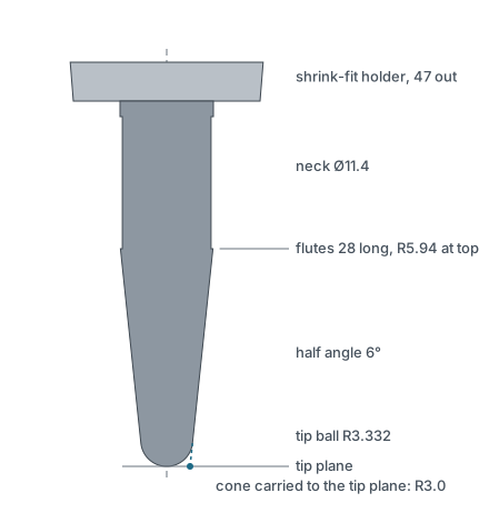
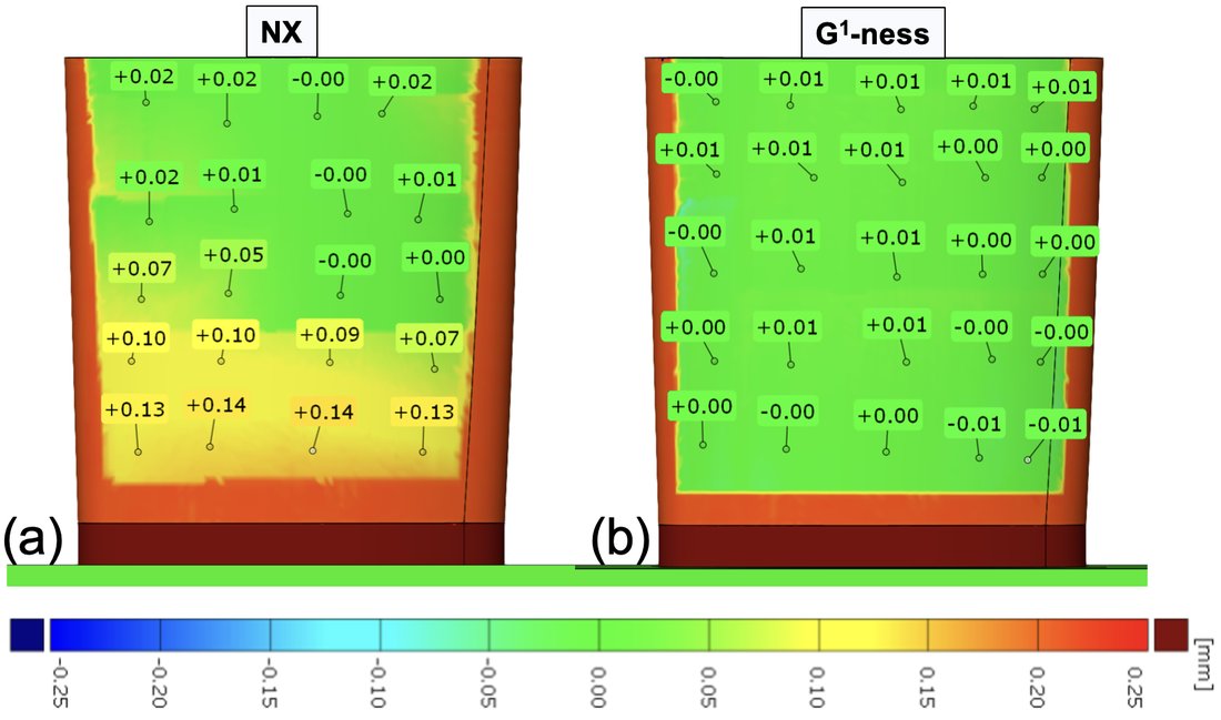
- A thin, blade-like part in a 60 × 50 × 60 mm block of AISI 1045 steel: three-axis roughing, five-axis ball-end semi-finishing all around the blade, then the face finished with the side of a conical cutter (a 6° taper, radius 3 mm), 19 mm deep per pass. The data set gives six Heidenhain TNC programs — roughing, semi-finishing, one finishing program from a commercial CAM system (NX) and three, one per pass, from the authors' own G1 algorithm — the blade as a NURBS surface, and the deviation both finishes left on the real part: up to +0.14 mm near the bottom for NX, within ±0.01 mm for G1. It gives no machine, fixture, holders, the sizes of two of the three tools, or where the blade sits in the programs.
The story
An AI agent worked from those files and HiNC running as a web service, driven only through its web API; it worked from HiNC's public documentation, and read HiNC's source only where a result needed explaining. It placed the blade in the programs' frame using the semi-finishing program alone, so the finishing programs could not be made to agree by construction; worked out the missing tools from the paths themselves; chose a generic five-axis B/C table-table machine and a riser that the G1 programs' own datum shift pointed to; and put every tool in a holder at a stick-out a shop would use. Before any simulation, a short script of its own swept the tapered cutter along every finishing pass and predicted the measured map. HiNC then played the programs themselves — roughing and semi-finishing once, both finishing branches from that recorded stock — and the agent read the finished face at the paper's 45 measuring points.
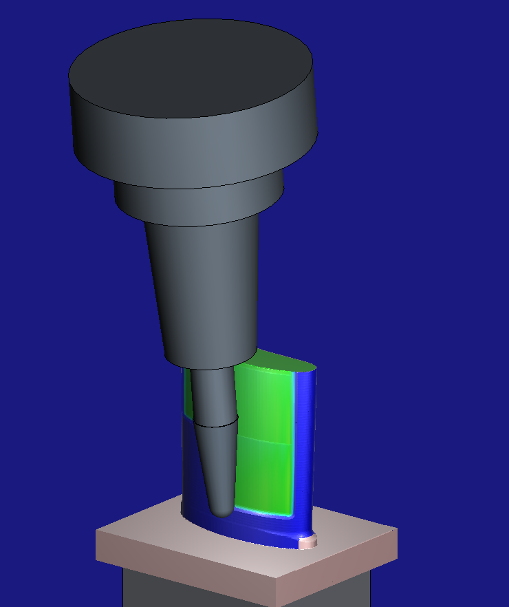
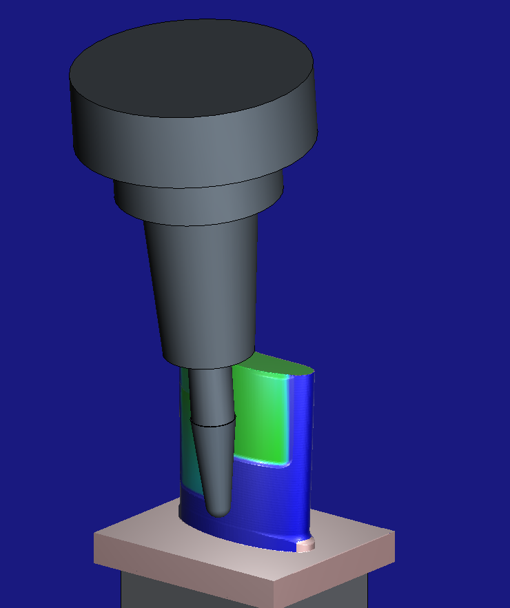
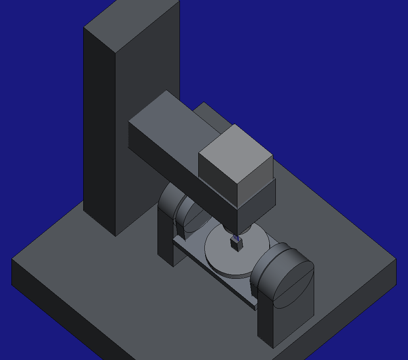
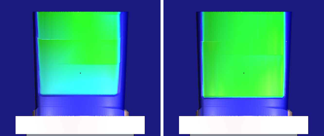
Pictures rendered by HiNC from the NC programs and blade model of K. Rajain et al., Zenodo 15830311, CC BY 4.0.
Four of its eleven dilemmas
The G1 programs call tool 0
On a TNC, tool 0 is the zero tool, of length 0, so the spindle's gauge point follows the path. On a machine the tool left in the spindle would hang 127 mm below that point, along a tilted axis that turns with the table, and no work offset can put the cut back. Played on its own, the published 04.1 left the simulated spindle with no tool: it cut nothing and drove the head into the part 61 times. The agent played copies that call tool 22, the conical cutter the NX program uses.
What does "a radius of 3 mm" measure?
Read as a tip ball of radius 3, the cutter stayed 0.28–0.30 mm off the design on the three G1 passes and the NX program's two upper passes, from 3 to 23 mm above its tip. A gap that does not grow with height is a radius error, not an angle error: 3 mm is where the 6° cone, carried down, meets the tip plane, and the tip ball has radius 3·cos 6°/(1 − sin 6°) = 3.332 mm. With that cutter the flank of every G1 pass sits within about −0.02 to +0.01 mm of the design.
Where is the blade?
The CAD and the programs use different frames and no transform is given. Fitting the blade to the finishing programs would make them agree by construction, so the agent fitted it to the semi-finishing program: its ball runs all around the blade at one constant distance. The fit came out as a swap of axes and a shift that puts the CAD's origin over the block's centre (30 and 25 mm, within 3 µm), with a 2.2 µm residual.
Known before cutting
The agent's own sweep of the cutter, written before any simulation and sharing no code with HiNC, already reproduced the NX half of the measured map to 0.002 mm on average: the +0.14 mm the paper measured is already in the geometry of the NX program's own passes. No deflection of tool or part is needed to explain it.
The other seven, among them a data-set file named as the finished face that is the other side of the blade, and a datum shift the case reads as coming from a preset on the rotary table's centre, with the riser sized to match, are in the full record.
The result
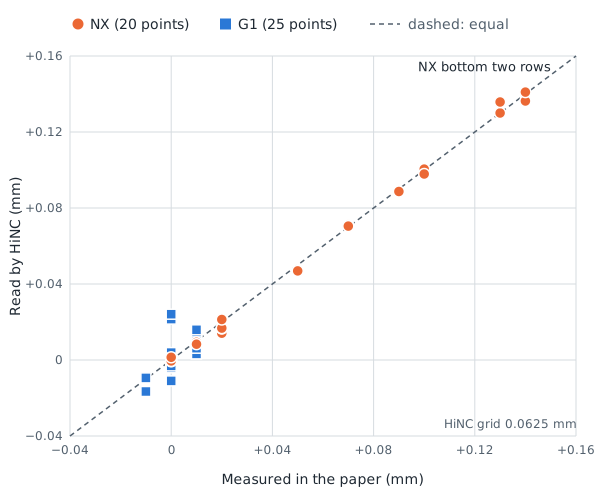
The whole chain — roughing and semi-finishing once, 197,265 steps, then both finishes from the stock it recorded, at 0.0625 mm — played every line with no collision and no rapid through material. At the paper's 45 measuring points the finished parts read the printed values to 0.0019 mm on average for NX and 0.0047 mm for G1; the NX bottom rows read +0.070 to +0.141 mm, where the paper measured +0.07 to +0.14, and the 25 G1 points stay within 0.024 mm. The agent's own sweep, written before any simulation, agreed with HiNC to 0.002 mm at every point. On a 32-thread server the roughing and semi-finishing took 1 h 54 min and each finish about two minutes, with 13.45 GiB of memory at the sampled peak. Asked, near the end of the roughing and semi-finishing, to watch long runs as they play, the agent checked alarms, contact and loads from then on and through both finishes; no check found an alarm. Everything here is simulated; the only real cut is the authors' own, whose measured map the simulation is compared with.
| Key number | What it is |
|---|---|
| 0.0019 mm | NX, 20 points: mean difference between HiNC's reading and the paper's measurement (largest 0.0059 mm) |
| 0.0047 mm | G1, 25 points: mean difference (largest 0.024 mm) |
| +0.070 to +0.141 mm | NX bottom two rows, the stock HiNC reads; the paper measured +0.07 to +0.14 mm |
| 0.0018 mm | largest difference, over all 45 points, between HiNC and the agent's geometric prediction written before any simulation |
| 1 h 54 min | roughing and semi-finishing, 197,265 steps, on the server; 34 min 55 s of simulated machining |
| about 2 min | each finish from the recorded stock (24.8 s and 21.6 s of simulated machining) |
What it brought
- For a machining engineer: the two finishing strategies told apart from their programs alone, before any metal was cut — the NX program leaves up to +0.14 mm on the lower face, the G1 program stays within 0.024 mm at the paper's 25 points. Once roughing and semi-finishing are recorded, each finishing variant costs about two minutes of server time on the recorded stock.
- For a teacher or a student: how the side of a conical cutter, swept along a five-axis path, can leave stock that grows towards its tip, how to read a catalogue's "radius of 3 mm" against the programs, how to place a CAD model with a program that runs around the part, and what a datum shift and a tool 0 say about how a program was run.
- For someone deciding whether to use an agent with HiNC: from public files to an accepted simulation with about 2,100 lines of the agent's own Python and a two-hour acceptance on a shared server. People set the rules, ruled which cases to keep and asked for long runs to be watched; the agent did the rest, and independent reviewer agents checked its written record claim by claim before it was published.
Read the full case record: BCAM thin blade
The data set and its backup
| Case | Original files | Backup of the originals |
|---|---|---|
| Thin blade, NX and G1 finishing | Zenodo 15830311 | Showcase-BCAM-Blade-G1Flank.zip |
The zip holds the nine original files as Zenodo serves them, under Source/,
with SOURCE.md and, under Setup/, the agent's scripts that place the blade, predict
the finish and write the case's geometry and G1 program copies, the generic machine and
case-numbers.json; the two meshes the scripts rebuild and the HiNC project itself are left out.
The original link may move; this site keeps a backup as far as the licence allows.