BCAM Blade: Two Five-Axis Flank Finishes Told Apart Before the Cut
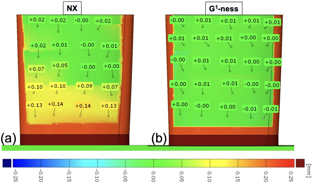
A research group at the Basque Center for Applied Mathematics and the University of the Basque Country published the programs behind a comparison: a thin, blade-like steel part finished with the side of a conical cutter, once by a program from a commercial CAM system (NX) and once by the authors' own multi-pass algorithm (called G1 here). They published the six Heidenhain programs, the blade as a NURBS surface, and a map of the deviation they measured on the finished face: the NX program left up to +0.14 mm near the bottom of the face, the G1 program stayed within ±0.01 mm. They did not publish the machine, the fixture, where the blade sits in the programs' frame, or the sizes of two of the three tools.
An AI agent set the case up from those files, the data set's short description of the conical cutter and the few facts the authors' paper adds. It placed the CAD in the programs' frame using the semi-finishing program, predicted the measured map from geometry before anything was simulated, and then built and played the project through the HiNC web API: roughing and semi-finishing once, both finishes from that recorded stock, at 0.0625 mm. The finished parts read the paper's 45 labelled points to 0.0019 mm on average for NX and 0.0047 mm for G1, with no collision. On the way the agent met eleven dilemmas. This page is the record, including the small problems.
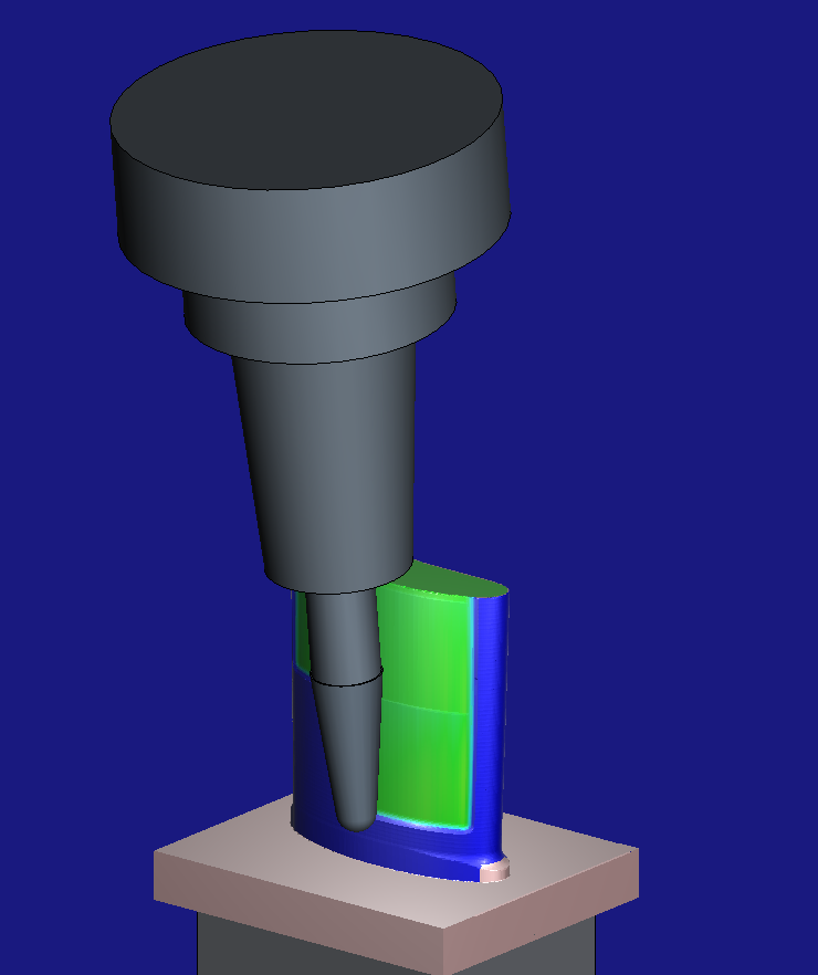
The case
The data set (Zenodo, 2025, CC BY 4.0) holds nine files:
- Six programs in Heidenhain TNC conversational format: a three-axis roughing (
01, tool 21), a five-axis ball-end semi-finishing that runs all around the blade (02, tool 24), the NX flank finishing in three passes (03, tool 22), and the authors' G1 finishing, one pass per program (04.1–04.3). All five-axis ones useM128(tool centre point management) and B/C rotary words. - The blade twice:
blade_full.obj, one trimmed bicubic B-spline surface (133 × 73 control points), andblade_front.obj, a triangle mesh. - The deviation map (the paper's Fig. 16): the finished face coloured from −0.25 to +0.25 mm, with 20 values printed on the NX half and 25 on the G1 half, to 0.01 mm. Neither the files nor the paper name the instrument that measured it.
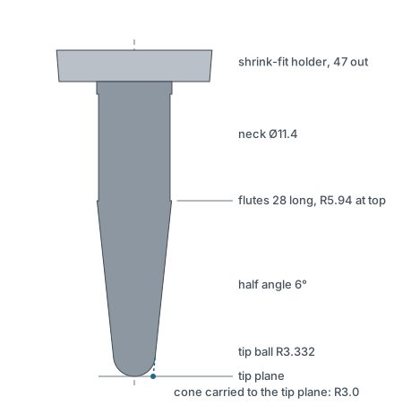
The record's description adds the conical cutter: it “has a taper angle of 6 degrees, a radius of 3 mm, 3 flutes, a cutting length of 28 mm, and an overall length of 83 mm”.
The authors' submitted version of the paper (read, not kept; its licence is non-commercial) adds a 60 × 50 × 60 mm block of AISI 1045 steel, the tool types, a cutting speed of 100 m/min, 0.03 mm per tooth, and 19 mm of axial depth per flank pass.
Left out: the machine and its kinematics, the fixture, where the block and the blade sit in the programs' frame, the diameters of tools 21 and 24, the holders, and how the G1 programs — which carry a datum shift and call tool 0 — relate to the NX program, which carries neither.
What the agent built
Each value is marked read (stated by the source), derived (worked out from it) or chosen (the agent's choice where the source is silent).
| Item | Value |
|---|---|
| Design model | blade_full.obj placed in the programs' frame (below) and meshed into a closed solid from the floor at Z −51.6 to the blade's top at Z −3.0, 141,116 triangles — derived; below the CAD's lower end (Z −47.95) its end section carried straight down to the floor — chosen |
| Where the CAD sits | NC = R·OBJ + t: OBJ Y → X, OBJ Z → −Y, OBJ X → −Z, t = (30, 25, 42.10) mm — derived from program 02 alone |
| Stock | 60 × 50 × 60 mm — read; X 0–60, Y 0–50, top at Z 0 — derived from the roughing's extents |
| Material | AISI 1045 — read; S45C, its JIS counterpart in HiNC's library — chosen |
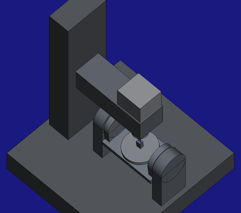
| Machine | a generic B/C table-table machine of plain blocks: B tilts the table about Y, C turns it; home and tool change at Z 600 — chosen |
| Fixture | a riser 86.6 mm tall, so the block's top is 146.6 mm above the C table — derived from the G1 programs' datum shift |
| Controller | Heidenhain; preset 1 on program zero, preset 2 on the C-table centre — derived |
| Tool 21 | flat end mill — read (paper); Ø18 — derived: at every roughing level from Z −5.86 down to the floor at −51.6 the tool centre keeps 9.496 mm from the blade, less the paper's 0.5 mm stock; flutes, lengths, stick-out, holder — chosen |
| Tool 24 | ball end mill — read (paper); Ø6 — derived from the fit of the semi-finishing path; flutes, lengths, neck, stick-out and holder — chosen |
| Tool 22 | 6° taper, radius 3 mm, 3 flutes, 28 mm cutting length, 83 mm overall — read (the record's description); a tapered ball end mill with 6° as the half angle, 3 mm as the flank radius at the tip plane and a tip ball R3.332 — derived from the programs; Ø11.4 neck, shrink-fit holder, 47 mm stick-out — chosen |
| Spindle | a generic motor spindle, 7.5 kW continuous up to 24,000 rpm — chosen |
| Speeds and feeds | 3,183, 13,793 and 5,305 rpm; 477 mm/min on the finishing passes — read from the programs |
| Programs | 01, 02, 03 byte for byte; 04.1–04.3 from copies with two lines changed (below) |
| Mission | roughing and semi-finishing once, the stock recorded; the NX and the G1 finishing each from that record, the geometry difference on, the finished part exported |
How the agent managed the work
- What counts as a pass, written down first. Before any simulation the agent committed six
criteria: all 25 G1 points within ±0.04 mm of the design; the NX bottom two rows at +0.05 mm or
more with a mean of +0.09 or more and its top two rows at +0.05 or less; the mean of the NX bottom
two rows at least 0.07 mm above the mean of the G1 bottom two rows; HiNC within 0.03 mm of an
independent geometric prediction at 40 or more of the 45 points; a clean run; and a record, not a
verdict, for the G1 program
04.1played as published (TOOL CALL 0). - A prediction before the simulation. The agent swept the conical cutter along every finishing pass in its own short script and measured the distance to the placed CAD. That calculation and HiNC share no code, so agreement between them is a cross-check of both.
- Trimmed runs first. The finishing programs were first played on a stand-in for the semi-finished blade — the design grown by the 0.48 mm the semi-finishing leaves — which costs seconds. Roughing and semi-finishing, 197,265 steps, ran once, at the acceptance resolution of 0.0625 mm, and both finishes were played from the stock it recorded.
- Sharing one server. The runs went to a private copy of the released HiNC on a shared Linux server where other agents were building other cases. Heavy runs queued on one shared lock. At its second launch the acceptance chain waited 21 minutes behind another case's acceptance run and then played nothing (the last dilemma); the third launch took the lock at once and ran under one hold of it: 1 h 54 min for the roughing and semi-finishing, then about 2 minutes for each finish.
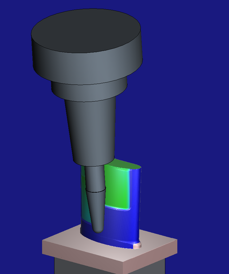
- Watching the run as it played. The owner asked that a long run be watched while it plays, not only judged at its end: a wrong program zero or a wrong tool offset does not stop a play — it keeps colliding, cuts air or cuts too deep for hours — while a small defect that does not spoil what follows can be noted and left to run. From then on the agent read the run every few minutes, more often during the short finishes, with requests that change nothing (the method is Replay Acceptance §2): the alarm counts and warnings, how many lines of each file had run, and over the last 4,000 steps the share of steps in contact with the stock and the peaks of force, stress ratio and spindle power. The last step's tool and line and the depth peak were added to the check afterwards. The advice came during the roughing and semi-finishing, which had one such check near their end; the NX finish had three while it played, and the G1 finish one just as it ended. Every check read no alarm, the finishing passes 72–74 % in contact, and loads inside the tool's and the spindle's limits. A picture of the canvas taken in the middle of a later finishing play shows the tool and the stock as cut so far.
- Where the owner stepped in. The case was one of fourteen collected together, most of them single-cutter experiments from papers. Once the trimmed runs had passed, the owner asked what those cases were for: the Showcase is for parts a production engineer recognises. The agent withdrew its acceptance chain from the queue before it started, and handed over a page with pictures, because a text-only report had not shown what the case was about. The owner ruled that the thin blade is a product case; the acceptance ran after that ruling.
- Independent checks of the written record. Before this page was published, five agents each checked one part of it, and of the company-site summary, against the case files and the run records, claim by claim — 322 claims. Of the problems each part raised, up to five went to a further agent told to refute them: 24 held and one was refuted. The agent weighed the other 25 itself. The corrections are on this page: a dilemma count, the word “scanned” for a map whose instrument is not named, a G1 range read off the flank instead of the finished face, the provenance of three tool rows, and the tool 0 evidence, which had put a tool in a spindle that had none. An earlier round of six refuters, before the acceptance, hit the account's usage limit and returned nothing.
The dilemmas
Each is told as the situation, the risk had it been missed, how it was noticed, the resolution, and the evidence that the resolution held.
Which file is the finished face?
- Situation. The data set calls the mesh
blade_front.obj, which reads as the machined front face. - Risk. Comparing the finished part with the wrong side of the blade.
- Noticed. Once the CAD was placed, every vertex of the mesh lay on the side that looks to +Y; all finishing passes run on the −Y side.
- Resolution. Use
blade_full.objinstead. Its surface closes around the blade and is trimmed at both ends, so capping the ends gives the whole blade as a solid. The mesh's triangles are about 2.5 mm apart on a face curved to about 45 mm radius, a chord error near 0.017 mm — as large as the G1 deviations, so it could not have served as the design anyway. - Evidence. The mesh's vertices lie on the NURBS surface, on the half with OBJ Z ≤ 0 (within 5 µm, apart from its rim, cut flat at OBJ Z = 0, up to 0.09 mm off); the finishing passes touch only the other half.
Where is the blade in the programs' frame?
- Situation. The CAD and the programs use different frames and no transform is given.
- Risk. Placing the CAD by fitting it to the finishing programs would make the G1 program “match” by construction.
- Resolution. Fit it to the semi-finishing program
02alone: its ball runs all around the blade at one constant distance, so the design surface is a constant offset of the ball centres. Started from the swap of axes the two bounding boxes suggest, the rigid fit stayed on it (within 7·10⁻⁵ rad) and on a shift of 30 and 25 mm in X and Y (within 3 µm) — the CAD's origin is the centre of the 60 × 50 mm block — with 2.2 µm residual. The height along the blade is the weakly determined direction (42.07–42.11 mm across the fits with ball radii 2 to 3.3 mm). - Evidence. With that placement, and before any simulation, the geometric prediction of the NX half of the map misses the 20 printed values by 0.002 mm on average and 0.008 mm at most.
What does “a radius of 3 mm” measure?
- Situation. With a 6° cone tangent to a tip ball of radius 3, the three G1 passes and the NX program's two upper passes all stay 0.28–0.30 mm away from the design — the same gap from 3 to 23 mm above the tip and along the whole chord.
- Risk. A cutter 0.3 mm too thin would still cut into the 0.48 mm left by semi-finishing, but take only about 0.19 mm of it, so the finishing would “leave” a uniform 0.3 mm layer that no program left.
- Resolution. A gap that is the same at every height is a radius offset, not an angle error (a wrong angle grows with height). So 6° is the half angle, and 3 mm is the radius where the cone, carried down, meets the tip plane — the way HiNC's general APT defines its diameter. The tip ball then has radius 3 cos 6° / (1 − sin 6°) = 3.332 mm. The alternative that the programs give the ball centre instead of the tip was tested on program 02 and fits five times worse. The project describes the cutter with the general APT, which states the tip ball and the cone explicitly (diameter 6, corner radius 3.332 centred on the axis 3.332 above the tip, beta 6°).
- Evidence. With that cutter the flank of every G1 pass sits within about −0.02 to +0.01 mm of the design, and the geometric prediction puts the finished G1 face at −0.016 to +0.025 mm at the paper's 25 G1 points. The catalogue number the paper names (06030B) could not be found online.
The sizes of tools 21 and 24
- Situation. The files say nothing about them; the paper says flat end mill and ball end mill.
- Resolution. At every roughing level from Z −5.86 down to the floor the tool centre comes within 9.496 mm of the blade; with the paper's 0.5 mm stock that is a Ø18 cutter. For the semi-finishing ball the fit residual is nearly flat from radius 2 to 3.3 (2.24–2.47 µm) and lowest at 3 (Ø6), which leaves 0.48 mm on the blade, not the paper's “up to 0.2 mm”; a 0.2 mm stock needs a radius near 3.4, between the fits at 3.3 (2.32 µm) and 3.5 (3.35 µm), where the residual starts to climb. The page reports the disagreement rather than choosing the paper's number.
- Evidence. The residual of the fit rises from 2.24 µm at radius 3.0 to 3.35 µm at 3.5 and 11.8 µm at 4.0. The roughing's top four levels sweep the whole block top, so the blade's top is at Z −3.0.
Two programs, two datums
- Situation. The G1 programs shift the datum by
CYCL DEF 7X−30 Y−25 Z146.6; the NX program has no shift. Yet both cover the same window in program coordinates. - Risk. On one preset the G1 passes land 30 and 25 mm away from the NX passes.
- Resolution. X−30 Y−25 is half the block, so the project reads the G1 programs as run from a
preset under the block's centre, 146.6 mm below its top, and takes that point to be the rotary
table's centre; the source does not say how the authors ran them. The project
keeps both presets: preset 1 on program zero for
01–03, preset 2 on the C-table centre for04.x, each activated from the mission withCYCL DEF 247, as an operator would from the preset table. The fixture is a riser that puts the block's top exactly there. The copies write the shift's first line, a bareCYCL DEF 7.0in the programs, asCYCL DEF 7.0 DATUM SHIFT, with the cycle name a TNC shows. - Evidence. HiNC put preset 1, on program zero, at machine (−30, −25, 46.6); preset 2, that plus (30, 25, −146.6), is then (0, 0, −100), the C table's top centre. The G1 and NX passes finish the same face.
Tool 0
- Situation. The G1 programs call
TOOL CALL 0. On a TNC, tool 0 is the zero tool, of length and radius 0; HiNC likewise compensates it with length 0, and keeps whatever tool is already in the spindle when the tool house has no tool 0. - Risk. Played as published, the spindle's gauge point follows the path. On a machine the tool left in the spindle hangs its whole length below that point — 127 mm for the conical cutter in its holder here — along the tilted axis, and that axis turns with C by 47° to 55° along a pass, so the tip's offset changes direction and no work offset can correct it.
- Resolution. The project plays copies in which
TOOL CALL 0calls tool 22, the same conical cutter the NX program uses — the change the programs need before they can cut where they were programmed; the source does not say what was run on the machine. - Evidence. The published
04.1, played once for the record on the stand-in stock with no tool in the spindle: no cutting step at all, and 61 collisions of the Z head with the part.
Home was inside the fixture
- Situation. The generic machine's home puts the spindle's gauge line at the rotary pivot, 100 mm above the table.
- Risk. A 127 mm tool starts with its holder inside the riser and its tip 27 mm below the table top.
- Noticed. The first trimmed run: 33 collision messages and a 29 kN force peak.
- Resolution. Home and the tool-change position at Z 600, as in the NIST five-axis case.
A tool too short for the rule
- Situation. The conical tool is 83 mm long overall and must reach 42.6 mm below the blade's top; the usual rule adds 5 mm of clearance for the holder.
- Resolution. 47 mm of stick-out with 36 mm clamped; sampled every millimetre of path and every 2° of rotation along all four finishing programs, the holder stays at least 5.15 mm from the semi-finished part. Above the flutes a Ø11.4 neck keeps the shank 0.26 mm clear of the finished face, where a plain Ø12 shank would rub.
Where were the measuring points?
- Situation. The map gives values, not coordinates.
- Resolution. Each printed value hangs on a leader line ending in a small ring. A ring template plus a test that only a leader line — not a neighbouring digit — lies next to the ring found all 45. Heights come from the face's top edge (the blade's top) and the top of the dark base strip (the lower end of the CAD blade); chord positions from the face's outline on each row. Seen with its right side as +X, the prediction matches the NX half to 0.002 mm on average; mirrored, to 0.021 mm.
Known before cutting
- Situation. The geometric prediction already reproduced the NX half of the map before any simulation: +0.07 to +0.14 mm on the bottom two rows, 0 to +0.02 mm on the top two.
- What it means. The +0.14 mm the paper measured is almost entirely in the NX program itself: the geometric sweep of its passes, with no deflection and no machine error, already leaves +0.07 to +0.14 mm on the lower face, growing towards the tip. No deflection of the tool or the part is needed to explain it.
An acceptance chain that did not run, twice
- Situation. When the owner's ruling came, the agent launched the acceptance chain in the background on the shared server and moved on to other work.
- Risk. Hours of waiting for a run that is not in the queue at all, or a chain that reports itself done having played nothing.
- Noticed. First, the chain's own log did not exist: the launch had named the script where the
private run folder is, not where the case's tools are, and the error went to a file nobody read.
Relaunched, it waited its turn and then logged the start and the end of all three plays within
the same second: the private HiNC instance had been restarted with no project open, so the first
request of each play was refused (
Player command is not a ListCommand). - Resolution. Open the project on the instance — the case's restart script now does it — and,
after any launch, read the log's first lines (the mission listing and
status Running) and the server's lock table before leaving. - Evidence. The third launch took the lock at once and logged 197,265 steps for the roughing and semi-finishing, 1 h 54 min later.
Results and benefits
Measured on HiNC 3.2.42 at a machining resolution of 0.0625 mm, one step per spindle revolution, on a 32-thread Linux server with 125 GB of memory. The two finishes start from the stock the first play recorded.
| Run | Steps | Simulated time | Run time | Peak force | Peak stress ratio | At the paper's points |
|---|---|---|---|---|---|---|
Roughing and semi-finishing (01, 02) |
197,265 | 34 min 55 s | 1 h 54 min | 724 N | 0.27 | — |
NX finishing (03) |
2,410 | 24.8 s | 2 min 5 s | 232 N | 0.52 | 0.0019 mm mean, 0.0059 mm largest difference from the printed values |
G1 finishing (04.1–04.3) |
2,011 | 21.6 s | 2 min 20 s | 507 N | 0.85 | 0.0047 mm mean, 0.024 mm largest |
G1 04.1 as published, on the stand-in at 0.25 mm |
0 | — | — | — | — | 61 collisions of the Z head with the part |
The private instance's resident memory peaked at 8.85 GiB over the roughing and semi-finishing, 11.73 GiB after the NX finish and at least 13.45 GiB by the end of the chain (sampled every 10 seconds; the last 9 seconds of the G1 finish, still rising, were not sampled). The spindle's power ratio peaked at 0.28 over the roughing and semi-finishing.
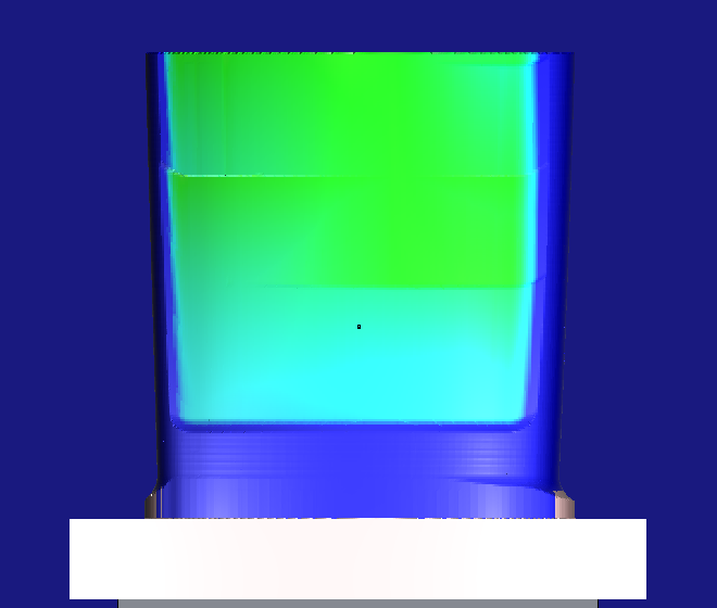
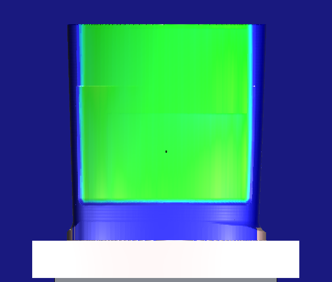

The same colour scale on both: blue is stock left (+0.25 mm and above), green is on the design, yellow to red would be cut too deep. The paper's own map colours the other way round.
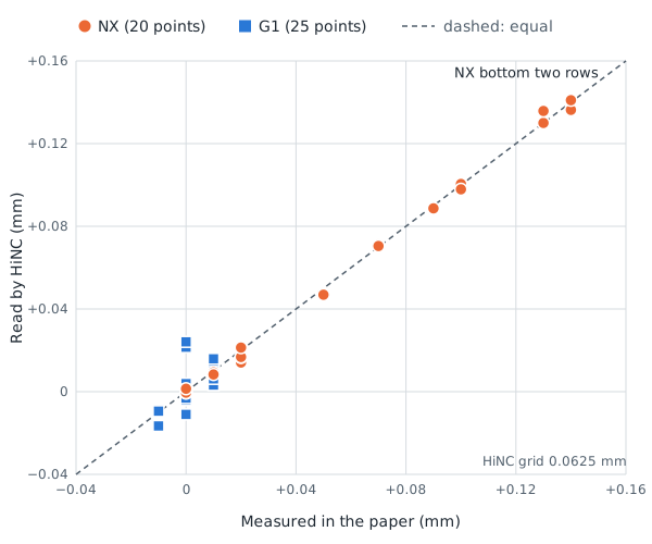
The 45 points one by one: the value the paper prints, HiNC's reading on the finished face, and the geometric prediction the agent wrote before any simulation, all in mm from the design (rows run from the blade's top down, points along the chord).
| Program | Row–point | Height Z | Paper | HiNC | Prediction |
|---|---|---|---|---|---|
| NX | 1–1 | −7.6 | +0.02 | +0.014 | +0.012 |
| NX | 1–2 | −9.2 | +0.02 | +0.017 | +0.017 |
| NX | 1–3 | −8.5 | −0.00 | −0.001 | −0.001 |
| NX | 1–4 | −8.5 | +0.02 | +0.017 | +0.016 |
| NX | 2–1 | −18.9 | +0.02 | +0.021 | +0.021 |
| NX | 2–2 | −17.5 | +0.01 | +0.009 | +0.010 |
| NX | 2–3 | −17.9 | −0.00 | −0.000 | −0.000 |
| NX | 2–4 | −18.7 | +0.01 | +0.008 | +0.008 |
| NX | 3–1 | −26.2 | +0.07 | +0.071 | +0.071 |
| NX | 3–2 | −25.5 | +0.05 | +0.047 | +0.047 |
| NX | 3–3 | −25.9 | −0.00 | −0.001 | −0.001 |
| NX | 3–4 | −26.3 | +0.00 | +0.001 | +0.001 |
| NX | 4–1 | −32.0 | +0.10 | +0.101 | +0.101 |
| NX | 4–2 | −32.1 | +0.10 | +0.098 | +0.098 |
| NX | 4–3 | −32.5 | +0.09 | +0.089 | +0.088 |
| NX | 4–4 | −32.8 | +0.07 | +0.070 | +0.071 |
| NX | 5–1 | −41.0 | +0.13 | +0.130 | +0.130 |
| NX | 5–2 | −40.4 | +0.14 | +0.136 | +0.136 |
| NX | 5–3 | −40.8 | +0.14 | +0.141 | +0.141 |
| NX | 5–4 | −40.8 | +0.13 | +0.136 | +0.136 |
| G1 | 1–1 | −7.2 | −0.00 | +0.004 | +0.004 |
| G1 | 1–2 | −7.6 | +0.01 | +0.014 | +0.014 |
| G1 | 1–3 | −8.1 | +0.01 | +0.013 | +0.013 |
| G1 | 1–4 | −7.7 | +0.01 | +0.009 | +0.009 |
| G1 | 1–5 | −8.1 | +0.01 | +0.003 | +0.003 |
| G1 | 2–1 | −14.3 | +0.01 | +0.009 | +0.008 |
| G1 | 2–2 | −14.4 | +0.01 | +0.014 | +0.015 |
| G1 | 2–3 | −15.2 | +0.01 | +0.008 | +0.008 |
| G1 | 2–4 | −14.4 | +0.00 | −0.002 | −0.002 |
| G1 | 2–5 | −14.5 | +0.00 | −0.001 | −0.001 |
| G1 | 3–1 | −23.7 | −0.00 | −0.002 | −0.002 |
| G1 | 3–2 | −23.4 | +0.01 | +0.014 | +0.013 |
| G1 | 3–3 | −24.1 | +0.01 | +0.016 | +0.016 |
| G1 | 3–4 | −23.8 | +0.00 | +0.021 | +0.022 |
| G1 | 3–5 | −23.8 | +0.00 | +0.024 | +0.025 |
| G1 | 4–1 | −32.0 | +0.00 | +0.001 | +0.001 |
| G1 | 4–2 | −32.4 | +0.01 | +0.009 | +0.010 |
| G1 | 4–3 | −32.1 | +0.01 | +0.006 | +0.006 |
| G1 | 4–4 | −31.8 | −0.00 | −0.011 | −0.011 |
| G1 | 4–5 | −32.2 | −0.00 | −0.002 | −0.001 |
| G1 | 5–1 | −40.0 | +0.00 | +0.000 | −0.001 |
| G1 | 5–2 | −40.4 | −0.00 | −0.004 | −0.004 |
| G1 | 5–3 | −40.8 | +0.00 | −0.003 | −0.003 |
| G1 | 5–4 | −41.1 | −0.01 | −0.017 | −0.016 |
| G1 | 5–5 | −41.5 | −0.01 | −0.009 | −0.009 |
| Criterion, written before the first play | Measured | Verdict |
|---|---|---|
| All 25 G1 points within ±0.04 mm of the design, with every G1 program cutting | largest 0.024 mm; 04.1, 04.2, 04.3 each ran every block (71, 71 and 76, the four lines of the datum shift counted as one), and the medians of the finished face's seven height bands lie between −0.004 and +0.011 mm (a pass that had not cut would leave its band at +0.48) |
pass |
| NX bottom two rows each +0.05 mm or more, mean +0.09 or more; top two rows +0.05 or less | +0.070 to +0.141, mean +0.113; top rows at most +0.021 | pass |
| Mean of the NX bottom two rows at least 0.07 mm above that of G1 | 0.116 mm: +0.113 for NX against −0.003 for G1 (the paper's printed values: 0.1125; the geometric prediction: 0.115) | pass |
| HiNC within 0.03 mm of the geometric prediction at 40 or more of the 45 points | 45 of 45; largest difference 0.0018 mm, mean 0.0005 mm | pass |
| A clean run | every block of every program ran (21,586, 21,057 and 514 in 01, 02 and 03); no collision, no rapid through material; the holder 5.15 mm from the part by the agent's check, and no holder collision in HiNC |
pass |
04.1 as published, a record |
on the stand-in at 0.25 mm: no cutting step; 61 collisions of the Z head with the part | recorded |
The trimmed runs came first: both finishes on the stand-in stock at 0.25 mm, one step per spindle revolution, about 20 seconds each.
| Trimmed run | Steps | Simulated time | At the paper's points | Peak force |
|---|---|---|---|---|
NX finishing (03) |
2,410 | 24.8 s | 0.0019 mm mean, 0.0052 mm largest | 243 N |
G1 finishing (04.1–04.3) |
2,011 | 21.6 s | 0.0048 mm mean, 0.024 mm largest | 486 N |
A step follows the feed per revolution, not the grid, so the steps and the simulated time are the acceptance's. At the 45 points the trimmed runs read within 0.0014 mm of the acceptance's values, so they had already given the answer in seconds.
- For a machining engineer. HiNC told the two finishing strategies apart from their programs alone, before any metal was cut: the NX program leaves +0.07 to +0.14 mm on the lower face, where the paper measured +0.07 to +0.14, and the G1 program stays within 0.024 mm at the paper's 25 points. Once the roughing and semi-finishing have been played and recorded, each finishing variant costs about two minutes of server time — the price of comparing CAM strategies on the recorded stock. HiNC's collision check, holder included, found nothing on any pass, and the agent's own check kept the holder 5.15 mm and the neck 0.26 mm off the part.
- For a teacher or student. Flank milling with a conical cutter: the side of the cone, swept along a five-axis path, can stand off the surface it is meant to finish, by an amount that grows towards the tip; how to read a catalogue's “radius of 3 mm” against the programs; placing a CAD model with a program that runs around the part; and what a datum shift and a tool 0 say about how a program was run.
- For someone weighing the approach. From the public files to an accepted simulation: about 2,100 lines of the agent's own Python (placement, prediction, set-up, play, judgement), a 2-hour acceptance on a shared server and seconds per trimmed run. People set the rules (holders at a shop's stick-out, public data only), ruled which cases the Showcase keeps and asked for long runs to be watched; the agent did the rest. Two launches that did nothing cost about four hours of waiting and no server time. Before publication, reviewer agents upheld 24 problems in the written record and the agent weighed 25 more; the corrections are on this page.
Honest limits
- The placement of the CAD is fitted, not given; its height along the blade varies by about 0.04 mm across fits (42.07–42.11 mm).
- The machine, the spindle, the fixture's shape and the holders are the agent's choices; the fixture's height and the diameters of tools 21 and 24 are worked out from the programs, not stated by the source. The machine's kinematic errors, the tool's runout and deflection, and the blade's compliance are not in the comparison.
- HiNC's finished part is compared with the design, not with the paper's measurement data: the exported part is measured along the design's normal at the 45 points, the paper's registration of its measurement is unknown, and a best-fit registration would hide a uniform offset.
- The paper prints its values to 0.01 mm, so agreement finer than about 0.005 mm at a point is within the rounding of the printed value.
- The largest cutting-depth reading of the roughing and semi-finishing, 48.6 mm, equals the blade's whole height (Z −3.0 to −51.6), where a roughing depth should match its 2.86 mm step-down. The run did not locate that step before its record was cleared; the loads over the same play stayed low (724 N, stress ratio 0.27), and the finished faces do not depend on it.
- The conical cutter's angle, radius, flutes and lengths are read from the data set's description; which angle the 6° is and where the 3 mm radius is measured are inferred from the programs; the catalogue sheet was not found.
- Two lines of each G1 program were changed to play them; the page says which and why.
What a reader can take to their own case
- Place a CAD model with a program that runs all around the part at a constant offset, not with the program you want to judge.
- A gap between cutter and design that is the same at every height is a radius problem; one that grows with height is an angle problem.
- Treat a published file's name (
blade_front.objhere) as a claim to check against the programs, not as a statement of which face was machined. - A datum shift and a tool 0 in one program, and none in another covering the same window, point to two presets and a tool the operator changed.
- Check a tapered cutter's APT values against the consistency relation on the Cutter Geometry page
before trusting its surface; a tapered ball end mill is a general APT, since a
TaperAptis sharp-cornered. - Read the per-step record (
DatumShift, tool offsets) when a run cuts in the wrong place, before changing the set-up. - Watch a long play while it runs — alarm counts, contact and loads over the latest steps — and stop it only for a set-up error that spoils what follows.
- Once a roughing and semi-finishing stage is recorded, compare finishing strategies on that stock in minutes each.
Source and licence
- Source. K. Rajain, G. Gómez Escudero, M. Bizzarri, H. Gonzalez Barrio, A. Calleja-Ochoa,
L. N. López de Lacalle, M. Barton, High-quality smooth finishing of blade-like geometries via G1
multi-pass 5-axis flank CNC machining using conical cutting tools, Zenodo (2025) —
https://zenodo.org/records/15830311; described in K. Rajain et al., The International Journal
of Advanced Manufacturing Technology 136, 4383–4397 (2025),
https://doi.org/10.1007/s00170-024-14898-6. If the links move, search for
zenodo 15830311or the title. - Licence. The data set: Creative Commons Attribution 4.0 International, https://creativecommons.org/licenses/by/4.0/. The published article is not open access and was not read. The facts this page takes from the paper beyond the data set (the block, the material, the cutting data, the tool types, the stock allowances and the figure number of the map) were read in the authors' submitted version in the BCAM repository, https://bird.bcamath.org/handle/20.500.11824/1905 (CC BY-NC-SA 3.0 ES), which was not kept and was used for nothing else; the published article may differ from it in detail.
- Attribution. NC programs, blade models and deviation map: K. Rajain, G. Gómez Escudero, M. Bizzarri, H. Gonzalez Barrio, A. Calleja-Ochoa, L. N. López de Lacalle, M. Barton, Zenodo (2025), https://zenodo.org/records/15830311, licensed CC BY 4.0, provided as-is and as-available without warranties. The pictures on this page are HiNC simulations of these programs and models.
- What was changed. The three G1 programs were played from copies with two lines changed each
(
TOOL CALL 0→TOOL CALL 22;CYCL DEF 7.0→CYCL DEF 7.0 DATUM SHIFT);blade_full.objwas placed in the programs' frame and meshed into a closed solid from Z −51.6 to −3.0, below the lower end of the CAD blade (Z −47.95 to −47.57) its end section carried straight down to the floor; the map's points were located on the image. The close-ups stop a play in the middle of the bottom pass, using copies of03cut after block 453 and of the G1 copy of04.3cut after block 46, each closed with its ownEND PGMline. Everything else was played as delivered. This site offers no download: the reader fetches the originals from Zenodo; the company site keeps a backup copy.
See Also
- Showcase — the other cases and how a case page reads
- Heidenhain Support — the klartext constructs these programs use
- Cutter Geometry — APT parameters, holder profile and stick-out
- Geometry Validation — the geometry difference
- Project Construction — the build order the agent followed
- Replay Acceptance over the HTTP API — the evidence a run is accepted on