Ball-end finishing of convex and concave faces in five raster directions
- Original source
- B. Mikó, B. Varga, W. Zębala, "The Effect of the Feed Direction on the Micro- and Macro Accuracy of 3D Ball-end Milling of Chromium-Molybdenum Alloy Steel", Materials 12(24), 4038 (2019) — doi.org/10.3390/ma12244038
- Search keywords
ma12244038,The Effect of the Feed Direction on the Micro- and Macro Accuracy of 3D Ball-end Milling- Licence
- CC BY 4.0
- Attribution
-
Test-part dimensions, cutting conditions and measured values after B. Mikó, B. Varga, W. Zębala,
Materials 12(24), 4038 (2019), https://doi.org/10.3390/ma12244038. © 2019 by the authors.
Licensee MDPI, Basel, Switzerland. Licensed CC BY 4.0, provided as is, without warranty. The part
models, the programs and the pictures were made by Tech Coordinate from the article, as the story
below and the zip's
SOURCE.mddescribe. - About the case
- Two 42CrMo4 steel blocks, one with a convex and one with a concave R45 face, finished with the same Ø10 mm four-flute ball end mill in five raster directions, from along the cylinder axis to across it; the article measured the roughness Rz and the form errors of each face and published them only as charts. It gives no model and no program.
The story
An AI agent was given the article and HiNC running as a web service, to be driven only through its web API and its public documentation. Missing: the part models, the ten finishing programs, the pre-finished stock, the tool's geometry beyond its diameter, the holder and the machine. The agent drew both parts from the article's drawing and trimmed each to a 10 mm band across the whole curvature, wrote the ten zig-zag programs itself, built the projects through the web API and played all ten. Before the first run it wrote down what would count as a pass and what it would compare; it then checked each number against a second one: the volume removed against the volume between stock and design, the cut surface against the design, the force against a later measurement by the same group, and the tool's bending against a beam formula.
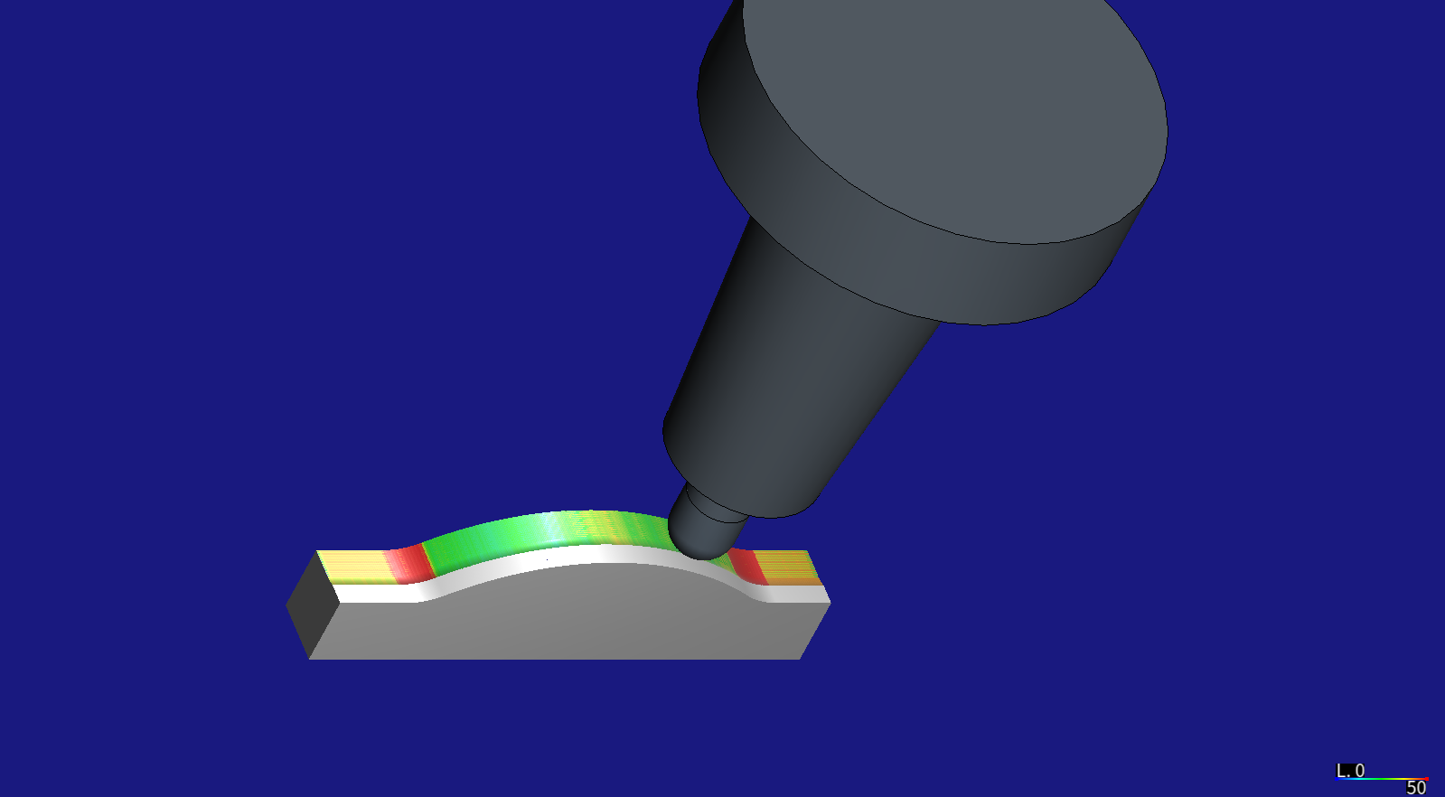
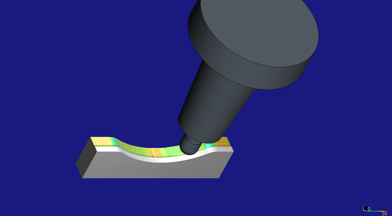
Pictures rendered by HiNC from models the agent drew after the drawing of Mikó, Varga and Zębala (CC BY 4.0).
Four of its thirteen dilemmas
Two papers, two sections
The article gives the face's normal range and R10 blends; a later paper on the same parts gives a height and a land width. With tangent blends the three cannot all hold. The agent built the article's own section, whose roughness positions confirm it, and recorded the difference: about a millimetre, in the blends only.
A tool with no data sheet
The maker's shop and catalogue no longer list the tool. A distributor's list of the maker's article numbers gave its shank, overall length and flute length; the helix, rake and edge hone were chosen as usual for a carbide ball end for steel and marked as chosen. Every direction uses the same tool, and the comparison is of rankings across directions.
Charts, not numbers
Every measured value is a point on a chart. A script read them from the images inside the PDF, by gridline and series colour; its first version was half a category off, which a check picture showed. The reading was then checked against the article's own regression equation, and agreed.
The agent's own mistake
The first coarse run reported collisions with the fixture. The cause was the agent's program: it cancelled the tool length and then moved to a safe height, which put the spindle, not the tip, at that height and the tip 100 mm lower. The programs now end at the safe height first, and every run since is clean.
The other nine, among them which force to compare with a measurement, a removal rate that counted several times the material, and a picture that needed a program of its own, are in the full record.
The result
All ten programs played to their last line with no warning and no collision, and 95 % of the cut surface lies within 2.7 µm of the design. The average cutting force changes by at most a fifth with the direction, 8.7 to 10.9 N; how much it swings along one pass changes far more, from 1 % along the cylinder axis to 31–49 % across it, and ranks the directions as the measured roughness does. The same group later measured the force across the cylinder, 10.6 to 14.9 N; the simulation gives 10.6 to 10.9 N. Along the surface normal, these forces move the modelled tool's tip by only a few hundredths of a micrometre, about a thousandth of the measured form errors of 10 to 53 µm. Each run took under two minutes on a 32-thread server. Everything is simulated; no part was cut.
What it brought
- For a machining engineer: for a given stepover, depth and feed, the raster direction changes the swing of the load along a pass far more than its level, and here the steadiest direction had the lowest measured roughness. A simulation ranks the directions by that swing before cutting; the form error is not the tool's deflection, is already large in the steadiest direction, and has causes outside what the simulation models.
- For a teacher or a student: the stepover cusp here is 0.56 µm while the measured Rz is 3–8 µm, so the roughness is not geometric; why the contact point moves on the ball when the raster crosses the curvature; and how to check a simulated force against a measurement that was averaged the same way.
- For someone deciding whether to use an agent with HiNC: a paper-only experiment rebuilt, its CAM programs written, and every number checked against a second one, so the result separates what a force model can answer from what it cannot. The runs took minutes; reading the papers took most of the work.
Read the full case record: ball-end finishing in five directions
The article and its backup
| Case | Setups | Original files | Backup of the originals |
|---|---|---|---|
| Ball-end feed direction | Convex and concave R45 faces, five raster directions each | the article | Showcase-Materials2019-42CrMo4-BallEnd.zip |
The zip holds the article as the publisher serves it, with the script that
derives the parts and programs from it and its values under Setup/.