End Mills Run to Breakage in Hardened 42CrMo4: Seven Set-Ups Ranked against Measured Tool Life
An open data set published in 2025 follows fourteen Ø10 mm end mills, each milled until it broke, in 42CrMo4 steel hardened to about 38 HRC. For every tool it gives the radial and axial depth of cut, the make, the holder length and the number of cycles the tool lasted. It publishes no NC program and no tool geometry beyond the diameter.
An AI agent built the first layer of all seven set-ups the data hold through the HiNC web API, modelled both tools from the catalogue that lists them, and wrote six pass criteria before the first play. Per cycle, the unit the lives are counted in, HiNC ranked the radial depth of cut as the tools' lives do, but by about 1.7 times where the lives differ 2.1–5.0 times; per layer, which removes nearly the same volume at either radial depth, it did not. It ranked the axial depth right at one radial depth and wrong at the other, told the two makes apart only through a helix angle the agent had to choose, and gave the long holder exactly the short holder's numbers. A review of the first runs found two errors in the agent's own build; both were fixed and every run was repeated. This page is the record, with sixteen dilemmas, the small ones included. Everything here is simulated, and HiNC does not count the cycles a tool survives.
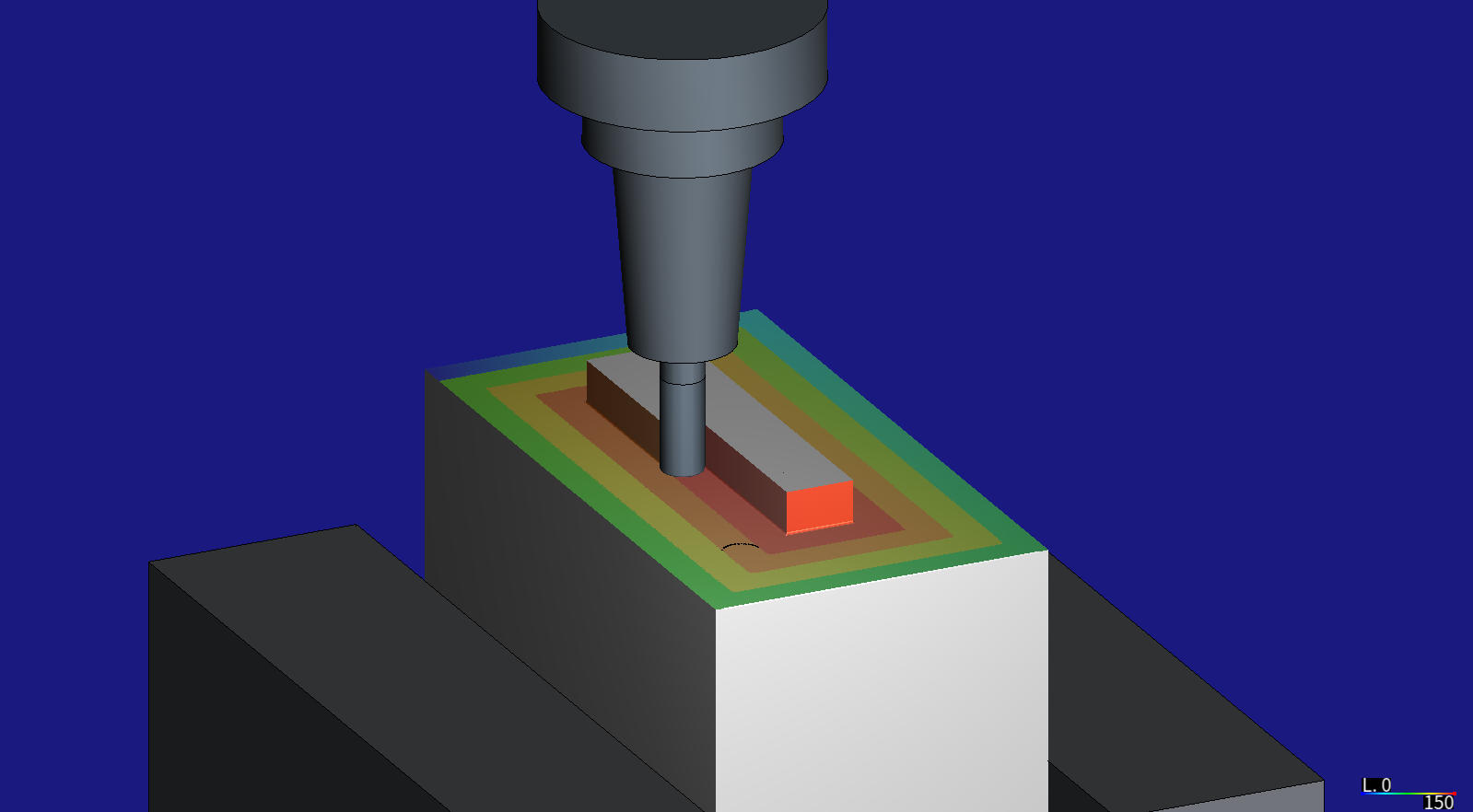
The case
The source is a data set on figshare and the article in Scientific Data 12, 650 (2025) that describes it, both by Grzegorz Piecuch and Tomasz Żabiński of Rzeszow University of Technology, Poland, both CC BY 4.0. A few terms first, as the page uses them:
- Radial depth of cut (RDOC) — how far the side of the cutter reaches into the material, measured across the cutter's axis; the makers' catalogues call it ae. Axial depth of cut (ADOC) — how deep the cutter reaches along its axis; ap in the catalogues, which give both in millimetres or as multiples of the cutter's diameter, d.
- Cycle — in this data set, one clockwise pass round the block at one radial step.
- Flank wear — the land worn on the cutter's flank, the face just behind each cutting edge. Its width, VB, is the usual measure of tool life. Crater wear — a hollow worn into the rake face, the face the chip slides over.
- Stress ratio — HiNC's yielding stress ratio: the largest stress the cutting forces of one spindle revolution cause in the cutter body, divided by the tensile strength of the flute material. Above 1 for longer than one step, HiNC expects the cutter to break, and well above 1, roughly 2, even at once (Evaluating Process Machinability).
- Mesh width — the size of the cells HiNC's model of the stock is made of, set as a run's machining resolution; a finer mesh resolves the cut more closely and costs more time and memory.
The article and the data state:
- Block. A cuboid of 80 × 80 × 150 mm, made to IT12 (an ISO tolerance grade), with 20 mm “excluded from cutting” and held in a vice. The text does not say which face is milled.
- Material. 42CrMo4 “heat hardened to 38 ± 2 HRC” (Rockwell C hardness); the samples measured 35.33 to 41.67 HRC. No composition or strength is given.
- Machine. A three-axis Haas VF-1. The CNC control is not named.
- Path. “A clockwise movement around the contour of the workpiece”, milled continuously without lifting the tool out of the material. Each cycle steps in by the RDOC: 4 cycles per layer at RDOC 8 mm, 7 at RDOC 4.5 mm. After a layer's last cycle the island left in the middle is planed and the tool goes down by the ADOC: 6 layers of 10 mm or 12 of 5 mm.
- Cutting conditions. 3,200 rpm and 640 mm/min for all 968 cycles. ADOC 5 or 10 mm. RDOC 4.5 mm, “not exceeding 45% of the tool diameter”, the maker's recommendation, or 8 mm, “which significantly exceeded” it.
- Tools. Ø10 mm end mills of two named products: type 1, Van Hoorn VHVTR41000701003050, and
type 2, PARA Tooling RS4 10,0×70. They were mounted in “thermal holders”, that is shrink-fit
chucks, with a
ToolHolderLengthof 80 or 160 mm. - Measured. For each tool, how many cycles it had left at each cycle (
CycleToFailure), so a tool listed at N ran N + 1 cycles. For each cycle, 120 statistics of eight accelerometers and twelve motor phase currents; the raw signals, about 25.3 GB, stay at the source. There is no cutting force, no flank-wear measurement and no roughness.
The seven set-ups the data hold, with the names this page uses for them (tool T1 is the VHVTR4 in the 80 mm chuck, T2 the RS4 in the 80 mm chuck, T3 the VHVTR4 in the 160 mm chuck):
| Set-up | RDOC | ADOC | Tool | Holder length | Cycles each tool lasted |
|---|---|---|---|---|---|
| R8-A5-T1 | 8 mm | 5 mm | VHVTR4 | 80 mm | 50, 41, 30 |
| R8-A10-T1 | 8 mm | 10 mm | VHVTR4 | 80 mm | 50, 54 |
| R45-A5-T1 | 4.5 mm | 5 mm | VHVTR4 | 80 mm | 116, 150 |
| R45-A10-T1 | 4.5 mm | 10 mm | VHVTR4 | 80 mm | 127 |
| R45-A5-T2 | 4.5 mm | 5 mm | RS4 | 80 mm | 85, 125 |
| R45-A10-T2 | 4.5 mm | 10 mm | RS4 | 80 mm | 84, 60 |
| R45-A10-T3 | 4.5 mm | 10 mm | VHVTR4 | 160 mm | 15, 1 |
The set-ups are read from the data; the cycle counts are derived, CycleToFailure + 1. The tool
that lasted one cycle failed in its first; the authors keep it as an outlier. The data never ran
RDOC 8 on the 160 mm holder, nor the RS4 on it.
The source leaves out the NC program, the corners and the approach of the contour, the flute count, helix, rake, corner form and lengths of the tools (four flutes can be counted on a photograph, Fig. 15a), the holder's shape and the stick-out, the coolant, the spindle's rating, and cutting data for 42CrMo4 at 38 HRC.
What the agent built
Each value is marked read (stated by the article, the data or a tool maker's catalogue), derived (worked out from read values) or chosen (the agent's choice where the sources are silent).
- Stock. A block 150 mm along X, 80 mm along Y, 80 mm tall. The size is read; which face is milled is derived from the article's figures (see the first dilemma). The lower 20 mm sits in the vice (read).
- Program zero. The centre of the block's top face, X along the 150 mm side (chosen).
- Fixture. A plain vice, a 220 × 180 × 80 mm body with two 20 mm jaws that clamp the block's lower 20 mm on its 150 mm faces (shape chosen). The jaw tops lie 50 mm below the deepest cut of layer 1 (derived).
- Machine. HiNC's shipped three-axis machine without a body model, placed mid-way in the VF-1's 508 × 406 mm travel with 610 mm from the spindle to the table (travel read, placement chosen).
- Controller. Fanuc dialect, metric (chosen; the article names no control).
- Spindle. 22.4 kW, 8,100 rpm and 122 N·m, the VF-1's published maximum rating (read, but only from secondary listings; see the dilemmas); constant torque up to 1,753 rpm and constant power above (derived); generic efficiency and idle values (chosen).
- Material. HiNC's SCM440 as shipped, which its library lists as EN 42CrMo4 and AISI 4140 (chosen; see the dilemma about its yield strength).
- Coolant.
M08with HiNC's default water-soluble coolant, a convection coefficient of 1,000 W/(m²·K) (chosen: both catalogues advise emulsion; the article does not say). - Programs. Layer 1 of each set-up, from the whole block: 4 cycles at RDOC 8, 7 at RDOC 4.5, at
S3200 F640 (read); the spindle started and stopped for every cycle (read from the current
traces of Figs. 11 and 12). Clockwise seen from above with
M03, so climb milling (derived). The tool centre runs round a sharp-cornered rectangle, one tool radius outside the island each cycle leaves (chosen). Each cycle plunges in the ring the previous cycle cleared (beside the block on cycle 1), on the −Y side of its own path's lower-left corner, corner 1, and 0.5 mm outside the previous cycle's path; it then feeds in +Y along the left side, so the cutter moves into the band along its length and the engagement grows from zero to the straight side's; it goes round, and back at corner 1 it leaves in −X along the bottom side's line (chosen; see the dilemma about the entry arc). The islands left are 86 × 16 mm and 87 × 17 mm (derived). Later layers and the planing between them are not simulated. - Speed and feed per tooth. 100.5 m/min and 0.05 mm per tooth (derived from 3,200 rpm, 640 mm/min, Ø10 mm and four flutes).
- Tools, from Van Hoorn Carbide's 2024 catalogue (printed pages 119, 123, 244 and 254) and its
webshop, which carry both lines:
- T1 and T3, VHVTR4 100 070 10 03 050. Ø10 mm, 0.5 mm corner radius, 4 flutes, 22 mm flute length, 70 mm overall, shank Ø10 h5 (a close ISO shaft tolerance), TiAlN GOLD coating, a variable helix with no angles given (read). Helix 35°, 38°, 35°, 38° on the four flutes, spaced evenly at the tip (chosen).
- T2, RS4 10,0×70. Ø10 mm, 4 flutes, 50° helix, 22 mm flute length, 70 mm overall, a 0.2 mm corner chamfer (read), drawn as a 0.2 mm radius because HiNC's column profile has no chamfer (chosen). The coating is PARA Silver+ in the catalogue and TiAlN in the webshop (read; the two disagree).
- Both. Radial rake 6° and relief 10° (chosen; no catalogue gives them); WC-Co10-600nm carbide and a 3 µm TiAlN coat (chosen). HiNC's default 30 µm edge hone, the small radius the edge is rounded to, and its default core for four flutes, 0.6 of the diameter — the core is the part of the cutter HiNC loads as a beam (chosen: HiNC's defaults kept, since no catalogue gives them).
- The makers' advice (read). VHVTR4, shoulder milling: ap below 10 mm, ae below 4.5 mm (0.45 d), 0.040–0.070 mm per tooth — the recommendation the article cites. RS4, contour roughing: ap up to 1.25 d, ae up to 0.40 d, 0.040 mm per tooth. RDOC 8 exceeds both; the RS4 at RDOC 4.5 and 0.05 mm per tooth already exceeds its own.
- Holders. Generic shrink-fit chucks with a Ø24 mm nose and a 4.5° taper (chosen), 80 mm (T1,
T2) and 160 mm (T3) long, reading
ToolHolderLengthas the gauge length (reading chosen). 30 mm stick-out on all three: the rule is this case series' own, “longer of flute length and cut depth, plus 5 mm, rounded up to 5 mm” (chosen), and it gives 22 + 5 = 27, so 30 (derived), which leaves 40 mm of the 70 mm tool in the bore. Tool lengths 110 and 190 mm (derived). At full depth the holder's nose stays 20 mm above the block (derived) (Cutter Geometry). - Mission. One program per play, each on a fresh blank; one step per spindle revolution; collision detection and physics on; a 0.25 mm mesh for coarse runs and 0.125 mm for acceptance (chosen). There is no target model, so no geometry difference.
How the agent managed the work
- Pass criteria before the first play. Before anything ran, the agent committed six criteria,
each with the outcome it expected, and the quantities they are judged on. For each cycle of layer
1: the increase in accumulated flank wear width and in crater wear, and the peak and the
straight-side median of the stress ratio, the spindle torque ratio (the torque the cut needs over
the torque the spindle can give at that speed), the force and the thermal yield ratio (HiNC's
long-term indicator of the cutting edge deforming under heat); a set-up's value is the mean over
its cycles.
- C1. RDOC 8 ranks above RDOC 4.5 in flank wear per cycle, peak stress ratio and peak torque ratio (VHVTR4, 80 mm, at both ADOCs). Expected: pass.
- C2. The flank-wear ratio RDOC 8 / RDOC 4.5 (VHVTR4, 80 mm, same ADOC) lies in the band of the lives' ratio, 2.1–5.0 (mean 2.91). Expected: fail low — at the same peak chip thickness, the contact angle passing 90° in both, the rate should grow about with the contact angle, the arc of each revolution an edge spends in the cut: 127° / 84° = 1.5.
- C3. HiNC ranks the ADOCs as the data do. Expected: fail.
- C4. HiNC separates the 160 mm holder from the 80 mm one. Expected: fail, every quantity within 1 %, because the holder is not in the beam HiNC loads and the stick-out is the same.
- C5. No ranking of the makes is claimed; a difference within ±10 % counts as “HiNC does not separate the makes”.
- C6. The stress ratio stays below 1 in every set-up. Expected: pass.
- Every run. Steps, material touched, every line executed, a depth peak equal to the ADOC, a width on the straight sides equal to the RDOC within the mesh width, and every message accounted for (Replay Acceptance over the HTTP API).
- Trimmed, coarse, then fine. A trimmed program, cycle 1 of R8-A10-T1 alone, checked program zero. Then all seven set-ups ran at 0.25 mm, 35 to 70 s each, and the acceptance at 0.125 mm, 135 to 285 s each. The mesh width was checked on that same cycle: the trimmed program at 0.125 and 0.0625 mm, and the first cycle of the full 0.25 mm run (at 0.125 mm the trimmed program and the full run give the same cycle 1, digit for digit).
- Probes where a difference needed a cause. One change at a time at 0.25 mm: the helix alone on R45-A10-T1, and the material's yield alone on R45-A10-T1 and R8-A10-T1.
- Checks the engine does not make, in the build script. The holder's nose is wider than the cutter, the stick-out covers the flutes, and the nose stays at least 5 mm above the block at full depth.
- Adversarial review. After the first round of runs, reviewer agents working from five angles checked the runs and the written claims against the run records, the article and the engine's source. They found that every peak sat on an entry arc the agent had chosen, that the relief angle never reached the force, heat and wear models, that a claim about the material's yield was wrong, that the article's current traces do not fit the path, and two errors in the criteria's own wording. The first runs were wrong in the first two ways. The programs and the build were fixed and every run was repeated. The criteria written before the first play were not changed: notes were added beside them, and every verdict on this page is judged against the criteria as written.
- No blind build. No second agent rebuilt this case from the written instructions.
- Sharing one server. The agent ran a private copy of the HiNC 3.2.42 web service on a shared server, reachable only from that machine, with sign-in off. Other agents took turns there for their own acceptance runs; see the dilemma about the shared queue.
- Where a person stepped in. Two of the owner's standing rulings shaped the work. A cutter is modelled from its maker's own data, never guessed from the work material; an earlier case in this series was withdrawn because its tool did not match the real one. And heavy runs on a shared machine go one at a time.
The dilemmas
Each dilemma is told as its situation, the risk, how it was noticed, the resolution, and the evidence. Unless a dilemma names the 0.25 mm runs or a probe, its measured numbers come from the acceptance runs at 0.125 mm on HiNC 3.2.42.
Which face, which way round, climb or conventional?
- Situation. The article gives an 80 × 80 × 150 mm cuboid but not the face the contour runs round. Its axis symbols in Figs. 5 and 6 are left-handed as drawn. It states neither the spindle direction nor climb or conventional milling.
- Risk. The wrong face gives the wrong path lengths and islands. The wrong direction swaps climb for conventional milling, where the chip is thin at entry instead of at exit.
- How it was noticed. Reading the figures against the text before writing any program.
- Resolution. The contour runs round the 150 × 80 mm face. The figures agree on it several ways:
Fig. 6 draws the block outline at 1.88 : 1, and 150 / 80 is 1.875; the islands in Fig. 6 scale to
86.8 × 17.2 mm and 86.0 × 15.9 mm, against 87 × 17 and 86 × 16 mm computed; Fig. 5 cuts 60 mm in
layers, which with the 20 mm in the vice makes the block 80 mm tall; the photograph in Fig. 10 has
those proportions. Reading the left-handed axes as table motions does not explain them (reversing
both table axes is a half turn, still right-handed), so only the word “clockwise” is used, seen
from above. Clockwise round the outside with
M03puts the material on the right of the travel: climb milling (derived). - Evidence it held. The seven programs leave the islands Fig. 6 shows.
Round corners or sharp?
- Situation. The article says only “clockwise around the contour”. Fig. 6, the solid rings in Fig. 12 and the ring marks in the photograph of Fig. 10 are rounded, widening outward; only the dashed path in Fig. 12 is sharp.
- Risk. Concentric rounded paths as Fig. 6 draws them never reach the block's corners, so every layer would leave a post at each corner; the photograph in Fig. 10 shows none. A tool centre going round a sharp island on R5 arcs fails too: at RDOC 8 the old island corner lies 8√2 = 11.3 mm from the new one along the diagonal, more than the 10 mm diameter, so each cycle would leave a 1.3 mm spike at every corner.
- How it was noticed. Laying out the cycles before writing the programs.
- Resolution. The tool centre runs round a sharp-cornered rectangle (chosen). At each corner the tool covers the old island corner, (8 − 5)√2 = 4.24 mm from its centre against a 5 mm radius, and the new island stays sharp. The rounded figures are recorded as evidence against this choice.
- Evidence it held. The islands match Fig. 6, which only confirms the block's orientation and the cycle count, since either corner form gives them. At the convex corners HiNC shows the load falling — to about a fifth of the straight-side force at RDOC 8 and ADOC 10, two fifths at ADOC 5, and to zero at RDOC 4.5 — and back to the straight-side value within 4–9 mm of travel, so the corners are not where any peak comes from. HiNC does not reproduce the current rises the article marks at the corners.
A tool known only by its product code
- Situation. The article gives Ø10 mm and two product codes; nothing about flutes, helix, rake, corner or lengths.
- Risk. A cutter that does not match the real one; an earlier case in this series was withdrawn for exactly that, and the owner has ruled that a tool is modelled from its sheet, not guessed from the work material.
- How it was noticed. A search for the codes found both lines in Van Hoorn Carbide's webshop and 2024 catalogue. The makers' STEP models are bodies of revolution, and their DXF side views are stylised: the RS4's flute lines measure 30° against the 50° stated. Neither gives a helix or a rake.
- Resolution. Both tools built from the catalogue. What it leaves out — rake, relief, carbide grade, the VHVTR4's helix angles — is marked chosen, and the chosen values are the same on both makes.
- Evidence it held. The STEP models confirm the lengths. In the model the two tools differ only in helix and corner, which is what later let a probe name the cause of their difference.
What “holder length 80 / 160” measures
- Situation. The data give
ToolHolderLength80 or 160 mm without saying what it measures; the article says only “thermal holders”. - Risk. A 70 mm tool cannot stick out 80 or 160 mm. Any reading that changes the stick-out changes the beam HiNC loads, and with it every stress ratio.
- How it was noticed. Setting up T3.
- Resolution. The value is read as the shrink-fit chuck's gauge length. Both chucks hold the tool at the same 30 mm stick-out.
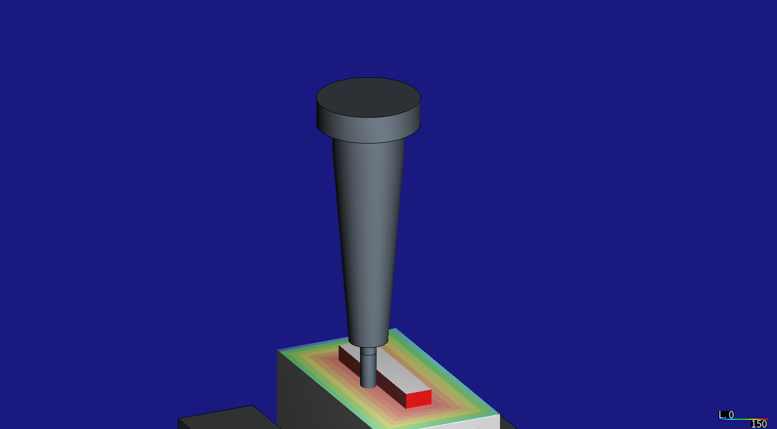
- Evidence it held. T3's cutter beam is identical to T1's, and every per-cycle quantity came out identical to the last digit. The only difference is that the 190 mm tool's rapid approach is 11 steps shorter, 13,830 steps against 13,841. That is the gap C4 predicted: HiNC does not see the holder under which the tools lasted 15 cycles and 1, against 127 in the 80 mm chuck. The picture below is at RDOC 4.5; its colours are to be read against the R45-A10-T1 row of the results table, not against the lead picture, which is at RDOC 8.
A spindle rating read second-hand
- Situation. The maker's website refused the agent's scripted reads.
- Risk. A torque ratio built on the wrong spindle.
- How it was noticed. The request was refused.
- Resolution. The VF-1's published maximum rating, 22.4 kW, 8,100 rpm and 122 N·m, as dealer and university equipment pages list it, marked as second-hand.
- Evidence it held. Every set-up runs at 3,200 rpm, where this rating gives 66.8 N·m (derived); another rating would scale every torque ratio alike, so no ranking depends on it, and at 0.05–0.14 no set-up comes near a stall.
“Raise SCM440's yield”
- Situation. The plan written when the case was selected said to raise the yield of HiNC's SCM440, since the shipped 785 / 950 MPa belongs to steel softer than 38 HRC.
- Risk. Changing the material without knowing what the yield reaches in HiNC. The agent's first write-up said it reaches nothing, and that was wrong.
- How it was noticed. In HiNC's source the yield enters neither the cutting force nor the stress ratio; it sets only the depth of plastic deformation in the workpiece. The review pointed out that this depth enters the thermal model: it changes how the deformation power splits between the chip and the work surface, and so the cutter's temperature and wear.
- Resolution. A material probe with the yield raised to 1,000 MPa in tension and 1,210 MPa in compression. On HiNC 3.2.42 at 0.25 mm, R45-A10-T1 wore its flank 5.5 % more per cycle, its crater 12.1 % more, and ran 22 °C hotter on its surface on the straight sides; R8-A10-T1 wore 5.1 % and 11.2 % more. Force and stress ratio did not change. The RDOC 8 / 4.5 flank ratio went from 1.691 to 1.685.
- Evidence it held. The RDOC 8 / 4.5 flank ratio does not depend on the yield; the wear values do. The comparisons of the ADOCs and of the makes were not probed, and both reach the flank wear through the same temperature the yield moves. The case uses SCM440 as shipped. If HiNC's forces are low for 38 HRC steel, the cause is its cutting coefficients, not the yield.
An entry arc that made every peak
- Situation. The first programs entered each cycle on a
G03arc of radius RDOC + 0.5 mm whose start pointed at the wall. The numbers below, up to the resolution, come from those first runs, at 0.25 mm on HiNC 3.2.42. - Risk. The arc cut into the cycle's band deeper than the straight side: HiNC read cutting widths of 7.4 mm at RDOC 4.5 and 9.0 mm at RDOC 8 on it, and every cycle's peak stress ratio, torque ratio and force sat there. Three of the first write-up's claims came from the arc: C6 failing at a stress ratio of 1.006, a peak at RDOC 4.5 of 1.4 times the straight-side value, and corner peaks running the same way as the article's.
- How it was noticed. The reviewers placed every peak step by step: all of them fell on the entry arc, steps 14 to 52 of each cycle.
- Resolution. The programs were rewritten to enter along the left side from below corner 1 and to leave along the bottom side's line, so the engagement never exceeds the straight side's. The criteria were not changed. Every run was repeated.
- Evidence it held. In the new runs, the 0.125 mm acceptance included, every set-up's peak stress ratio, torque ratio and force equal its straight-side values. C6 went from fail to pass because the program no longer overloaded the cutter; its threshold stayed at 1.
A relief angle that never reached the models
- Situation. The first build wrote the 10° relief only on the flute contours.
- Risk. HiNC's force, heat and wear models read the cutter's own relief angle, which stayed at HiNC's default of 5°. Flank wear width is the wear depth divided by the tangent of the relief, plus smaller terms, so every flank value was off.
- How it was noticed. The review read the engine's source: the force and heat calculations and the thermal kernel's wear width take the cutter-level value.
- Resolution. The build now also sets the cutter's relief to 10° and its hone to 30 µm through
PUT /api/Cutter/{id}/general. The project was rebuilt and every run repeated. - Evidence it held. The 0.25 mm runs on HiNC 3.2.42 compare the first round with the second, and between them both the relief (5° to 10°) and the entry (the arc to the straight entry) changed; no run changes the relief alone. Together the two changes multiplied every set-up's flank wear width per cycle by 0.72–0.73, so the width at 10° is about 0.73 of the width at 5°. That is less of a drop than the tangents alone would give (tan 5° / tan 10° = 0.50), partly because on the narrower land the wear depth per cycle grew about 1.36 times as fast. The RDOC 8 / 4.5 ratio hardly moved: 1.68–1.70 before, 1.67–1.69 after.
The core of the cutter is HiNC's default
- Situation. HiNC loads the cutter as a round beam whose core is a fraction of the diameter. Its flute-count default gives 0.6 for four flutes, a value its source says was found on the web. Read back through the web API right after the fluting is set, the ratio is 1, because no flute has been added yet; it reads 0.6 once the four flutes are in.
- Risk. The stress ratio goes with the inverse cube of the core diameter: a ratio of 0.55 multiplies it by 1.30, 0.65 by 0.79. Every absolute stress ratio, C6 included, carries this value.
- How it was noticed. Reading back the cutter after every call of the build.
- Resolution. The default is kept and recorded as an assumption (Cutter Adjustment Levers shows how to change it).
- Evidence it held. The finished build reads 0.6. The ranking by stress ratio does not depend on it, since all three tools carry the same ratio.
Current traces that do not fit the path
- Situation. Fig. 12, the spindle current of a third cycle, shows the spindle running about 27.5 s and loaded for about 13 s. The third RDOC 8 cycle's ring is 308 mm, 28.9 s at 640 mm/min, or 325 mm and 30.5 s with its entry and exit (derived): longer than the spindle runs, and more than twice the time under load. The corners marked on the trace are 1.3, 4.4 and 1.6 s apart where the sides would take about 4, 10.5 and 4 s. In Fig. 11, a first cycle, the current stays near idle for about 35 s. The text introduces both as RDOC 4.5 runs, but their sample is an RDOC 8 run.
- Risk. The wear per cycle rests on the reading that one cycle is one full ring at 640 mm/min. If it is not, every absolute per-cycle value moves.
- How it was noticed. The review compared the traces' timing with the programs.
- Resolution. Recorded as a limit: the feed, the time axis or the path differs from this reading. The two figures are used only for what they show clearly — the spindle starts and stops every cycle, and the authors marked the corners. Any later comparison with the measured current has to align the times first.
- Evidence it held. None either way; the question stays open (see Honest limits).
Flank wear that slows down every cycle
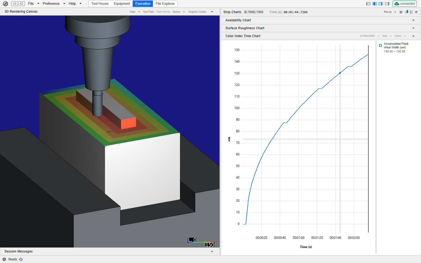
- Situation. In every set-up the flank wear added per cycle falls from cycle to cycle: 88, 30, 19 and 13 µm at R8-A10-T1. Crater wear grows roughly with the length cut.
- Risk. The two RDOCs run different numbers of cycles of different lengths, so a mean per cycle mixes the steep start with the flat tail. A reader could also take the flattening curve as a sign of long life; HiNC's flank never speeds up before a break.
- How it was noticed. The per-cycle series. The review fitted the four T1 set-ups: the wear width grows about as the length cut to the power 0.48.
- Resolution. It is a property of the model. In HiNC's source the flank pressure is a fixed edge term plus a term in the minimum uncut chip thickness — a constant of the edge, set by its hone, not the chip the feed makes — divided by the width of the wear land, and that width is the accumulated wear; the wider the land, the slower it grows. That pressure feeds the wear law of Tool Life and Wear. C2 is judged as written. Beside it, computed after the runs and not a criterion, the page reports the ratio of the lengths each RDOC needs to reach the same flank wear width — tool life being the length to a wear limit: 1.63–1.70, close to the per-cycle ratio and still below 2.1.
- Evidence it held. The length ratio, 1.63–1.70, agrees with the per-cycle ratio, 1.67–1.70, so the choice of measure does not change C2's verdict. The Color Index Time Chart shows the shape.
A cutting width wider than the radial depth
- Situation. The per-run criterion asks for a straight-side cutting width equal to the RDOC within the mesh width. Cycle 1 reads exactly 8.0 and 4.5 mm. Later cycles read 8.17 and 4.67 mm with T1 and T3, and 4.515 mm with T2.
- Risk. A path offset by 0.17 mm, or a width check passed by mistake.
- How it was noticed. The acceptance check of every run: it fails for the five set-ups with the VHVTR4.
- Resolution. The previous cycle's corner radius leaves a small fillet at the foot of the wall. One mesh cell above the floor, at a height of 0.124 mm, just under the 0.125 mm cell, that fillet is r − √(r² − (r − 0.124)²) wide, with r the corner radius: 0.17 mm for the VHVTR4's 0.5 mm radius, 0.015 mm for the RS4's 0.2 mm (derived). The width check fails as written, and the cause is geometric.
- Evidence it held. The derived widths match the measured ones for both tools, and HiNC's removal rate on the straight sides matches RDOC × ADOC × feed: 853.2 mm³/s measured against 853.3 mm³/s derived at R8-A10, 240.1 against 240.0 at RDOC 4.5 and ADOC 5.
The axial depth ranked right at one radial depth only
- Situation. In the data, the deeper ADOC of 10 mm lasted longer at RDOC 8 (a mean of 52 cycles against 40.3) and shorter at RDOC 4.5 (VHVTR4: 127 against 133; RS4: 72 against 105).
- Risk. Reading a partial agreement as a match.
- How it was noticed. C3 is judged on every quantity, crater wear included, with no tolerance. HiNC ranks ADOC 10 as harder on the cutter on every one: flank wear 4.5–6 % more, crater 10.5–13.5 % more, straight-side stress ratio 1.42–1.67 times and force 1.59–1.90 times as high, and the cutter's surface 18–25 °C hotter.
- Resolution. C3 fails as written: the two pairs at RDOC 4.5 agree with the data on every quantity, and the pair at RDOC 8 disagrees on every quantity — flank 1.06, crater 1.13, stress ratio 1.63 and force 1.87 times. The criterion predicted the failure but not its shape: it expected the wear to double with the ADOC, and the flank wear moved only 4.5–6 %. That expectation was itself naive: a flank wear width is measured at each point of the edge, and a deeper ADOC lengthens the engaged edge rather than loading each point more. In HiNC the flank pressure comes from the edge and the wear land alone, as the dilemma about flank wear that slows down every cycle describes: it depends on neither the cutting force nor the feed per tooth, so the ADOC reaches the flank wear only through the temperature. What the data contradict is the direction of the RDOC 8 pair, not the size of the step.
- Evidence it held. The same ordering at 0.25 mm and at 0.125 mm.
Two makes: told apart by a value read, or by one chosen?
- Situation. T2, the RS4, wears more than T1: flank 18–19 % and crater 42–43 % more per cycle. The data rank it the same way: the RS4 tools lasted less.
- Risk. Presenting the consequence of a chosen value as a finding.
- How it was noticed. The C5 comparison, then a probe to find the cause.
- Resolution. On R45-A10 at 0.25 mm on HiNC 3.2.42, T1 was given four 50° flutes, once as four separately defined flutes and once through HiNC's single setting for evenly spaced identical flutes. Both runs gave identical results: flank 26.03 µm and crater 36.84 µm per cycle, straight-side stress ratio 0.733, force 1,556 N and surface temperature 608 °C. T2 gave 26.1 µm, 35.9 µm, 0.735, 1,565 N and 604 °C; T1 as built, 22.1 µm, 25.7 µm, 0.604, 1,224 N and 526 °C. The helix accounts for almost all of the difference; the corner accounts for the last 3 % of crater and 4 °C. The path runs from the helix to the cutter's surface temperature, and from the temperature to the coating's wear coefficient and hardness in HiNC's wear law (Tool Life and Wear). The hottest set-up already exceeds the 600 °C end of the coating's wear table, where the coefficient is held at its last value.
- Evidence it held. HiNC tells the makes apart almost entirely by the helix. The RS4's 50° is read; the VHVTR4's 35° / 38° is chosen. C5 claimed no ranking, so the matching direction is not evidence. The RS4 at RDOC 4.5 already ran outside its own maker's advice, which may be another reason for its shorter life, and one HiNC does not cover.
A shared queue, and a kill command that hit its own connection
- Situation. The agents on the shared server took turns for acceptance runs through a lock file. A batch of runs at a 0.03125 mm mesh with geometry differences held the lock for hours.
- Risk. Waiting hours for light runs, or starving the other agents' runs by running beside them.
- How it was noticed. The agent's own batch sat in the queue behind it.
- Resolution. The coarse runs (35–70 s, each adding at most 1.7 GB to the service process) and the 0.125 mm acceptance (135–285 s, each adding under 2 GB to a process that held about 2.6 GB) are light, so they ran outside the lock, one at a time, each after checking that at least 30 GB of memory was free. Stopping its own queued batch, the agent killed by name pattern: the pattern matched its own remote-shell command line and cut the connection, while the queued script, started under a shorter name, survived. For a while two copies were queued, and one was later restarted by someone else. The agent then identified its own processes by their working folder and killed them by exact process number, parent first.
- Evidence it held. The acceptance runs completed one at a time, each in 135–285 s of server time.
A borrowed build, a shared clone and a rewritten spindle file
- Situation. Three small problems. The agent's private copy of the service needed a HiNC build, and the agent had none of its own on the server. The local clone of the case repository is shared with other agents, who committed and pushed after the agent's first commit, so the agent's push looked lost. And HiNC rewrote the spindle file in its own newer format at the first save, from 3,245 to 4,131 bytes.
- Risk. Running an unknown build; a lost commit; a project whose spindle file differs from the one committed.
- How it was noticed. Setting up the private copy; the history of the shared clone; the file's size after the save.
- Resolution. The HiNC 3.2.42 build came from another agent's private copy.
git merge-base --is-ancestorconfirmed that the commit was in the pushed history. HiNC's version of the spindle file was committed with the project. - Evidence it held. The Execution page shows v3.2.42; the commit is an ancestor of the remote branch; the rewritten spindle file carries the same values.
Results and benefits
Everything here is simulated; nothing was cut. Measured on HiNC 3.2.42 at a 0.125 mm mesh, one
step per spindle revolution, on a private copy of the HiNC web service on a shared server. Per-cycle
values are means over the cycles of layer 1. The stress ratio's peak equals its straight-side value
in every set-up; force and temperature are straight-side medians. The cycles lasted are derived
(CycleToFailure + 1). Each layer is planar and every plunge is in cleared space, so the flank wear
width is used within the planar cutting it is valid for (Tool Life and Wear).
| Set-up | Cycles lasted | Flank wear per cycle | Flank after layer 1 | Crater per cycle | Crater per metre | Stress ratio | Torque ratio | Force | Surface temp. |
|---|---|---|---|---|---|---|---|---|---|
| R8-A5-T1 | 50, 41, 30 | 35.2 µm | 140.7 µm | 32.6 µm | 91.0 µm | 0.553 | 0.084 | 992 N | 519 °C |
| R8-A10-T1 | 50, 54 | 37.3 µm | 149.2 µm | 37.0 µm | 103.3 µm | 0.900 | 0.144 | 1,853 N | 543 °C |
| R45-A5-T1 | 116, 150 | 21.0 µm | 147.0 µm | 23.1 µm | 63.0 µm | 0.425 | 0.053 | 770 N | 506 °C |
| R45-A10-T1 | 127 | 22.0 µm | 153.9 µm | 25.6 µm | 69.7 µm | 0.604 | 0.087 | 1,224 N | 524 °C |
| R45-A5-T2 | 85, 125 | 24.9 µm | 174.3 µm | 33.0 µm | 89.8 µm | 0.438 | 0.053 | 819 N | 576 °C |
| R45-A10-T2 | 84, 60 | 26.0 µm | 182.2 µm | 36.4 µm | 99.1 µm | 0.732 | 0.100 | 1,554 N | 601 °C |
| R45-A10-T3 | 15, 1 | 22.0 µm | 153.9 µm | 25.6 µm | 69.7 µm | 0.604 | 0.087 | 1,224 N | 524 °C |
Crater is the crater's depth; “per metre” divides each cycle's crater by that cycle's length of tool
path, entry and exit included. Force is the largest force on the cutter in a step, HiNC's
MaxAbsForce_N. Surface temp. is the cutter's own surface temperature. The torque ratio is the peak,
which equals the straight-side value.
The first cycle wears the flank most: 82.4, 87.6, 66.7, 70.2, 79.7, 83.6 and 70.2 µm in the order of the table. The runs took 7,830 and 7,926 steps and 2 min 19 s and 2 min 21 s of simulated time at RDOC 8, and 13,673 to 13,841 steps and 4 min 8 s to 4 min 12 s at RDOC 4.5.
The criteria, judged as written before the first play:
| Criterion | Expected | Verdict on HiNC 3.2.42 |
|---|---|---|
| C1 — RDOC 8 above 4.5 | pass | Pass. Flank wear 1.67 and 1.70 times, stress ratio 1.30 and 1.49 times, torque ratio 1.58 and 1.66 times (ADOC 5 and 10). |
| C2 — flank ratio within 2.1–5.0 | fail low | Fail. 1.67–1.70. It also misses the bands the review worked out for each ADOC alone, 2.32–5.00 and 2.35–2.54. |
| C3 — the ADOC ranking | fail | Fail. The two RDOC 4.5 pairs agree on every quantity; the RDOC 8 pair disagrees on every quantity. |
| C4 — the 160 mm holder | fail | Fail. Every quantity 1.000 times the 80 mm holder's. |
| C5 — the makes, no ranking claimed | — | Differences beyond ±10 %. Flank +18–19 %, crater +42–43 %; at ADOC 10, stress ratio +21 % and force +27 %; at ADOC 5, stress ratio +3 % and force +6 %, of the same size as the change between the 0.25 and 0.125 mm meshes (at 0.25 mm, +0 % and +3 %). |
| C6 — stress ratio below 1 | pass | Pass. Highest 0.900, R8-A10-T1. |
The review added notes beside the criteria without changing them: the band in C2 mixes the two ADOCs, and its reasoning that both contact angles pass 90° was wrong (127° at RDOC 8, 84° at RDOC 4.5, derived), though the peak chip thickness still differs by only 0.5 %; C3 is judged with no tolerance on every quantity; beyond helix and corner, the catalogues also differ in coating and in the makers' advice, which the model does not carry; and the data resolve a failure to a cycle, not a revolution: the tool that lasted one cycle failed somewhere in its first.
Computed after the runs, not part of the criteria:
- Length to equal flank wear. RDOC 4.5 needs 1.63–1.70 times the length RDOC 8 needs to reach the same flank wear width, against lives 2.1–5.0 times as long. The common widths are 100 µm and 1 µm short of the RDOC 8 set-up's width at the end of layer 1, 139.7 µm at ADOC 5 and 148.2 µm at ADOC 10 (chosen) — all well below the 0.3 mm commonly used as a flank wear limit.
- Per layer instead of per cycle. A layer removes nearly the same volume at either radial depth: 10,624 mm² of the 150 × 80 mm face at RDOC 8 and 10,521 mm² at RDOC 4.5, times the ADOC (derived). After layer 1, HiNC's flank is slightly wider at RDOC 4.5 than at RDOC 8: 147.0 against 140.7 µm at ADOC 5, 153.9 against 149.2 µm at ADOC 10. The data's RDOC 4.5 tools lasted 1.4–1.9 times as many layers as the RDOC 8 ones (VHVTR4, 80 mm, same ADOC; derived: cycles lasted over cycles per layer). Per volume removed, HiNC does not rank the radial depth as the data do.
- Rank correlation with the mean life (Spearman's ρ, six set-ups without the 160 mm holder; −1 would mean that a higher value goes with a shorter life in every pair). Flank wear per cycle −0.94; one pair out of order away from a perfect inverse ranking, and that pair is C3's, the two ADOCs at RDOC 8. RDOC alone gives about −0.83. All of the gain over the radial depth alone comes from putting the RS4 above the VHVTR4 at RDOC 4.5, and that order rests on the VHVTR4's chosen helix: with the two makes tied at each ADOC, flank wear would give about −0.79 (derived); the four VHVTR4 set-ups in the 80 mm chuck alone give −0.80. Crater per metre −0.83, crater per cycle −0.66, stress ratio and force −0.54, torque ratio −0.43, thermal yield ratio and surface temperature −0.26. With the 160 mm holder included, flank wear drops to −0.52. With six points, these are indications, not proof.
The checks behind the numbers, all on HiNC 3.2.42:
- Mesh width. Cycle 1 of R8-A10-T1 — the full program's first cycle at 0.25 mm, the trimmed program at 0.125 and 0.0625 mm — gave a force of 1,842, 1,853 and 1,848 N, a stress ratio of 0.895, 0.900 and 0.898, flank wear of 87.9, 87.6 and 87.5 µm and crater of 47.9, 47.7 and 47.6 µm: at most 0.6 % apart. Every cell of the table differs by 3 % or less between the 0.25 mm runs and the 0.125 mm acceptance.
- Every run. Every line executed (58 or 94); the depth peak equal to the ADOC; no warning and no error. Each run's messages were only progress and success notes (the first run after a rebuild also a collision-preparation pair) and one line-count note from the NC reader; no step message. The width check fails as written on the VHVTR4 set-ups for the geometric reason given in the dilemmas.
- Thermal yield ratio. 1.40–1.70 on the straight sides, above 1 in every set-up, at surface temperatures of 506–601 °C. HiNC's documentation expects this at makers' recommended conditions, because its tool-material defaults are conservative (Evaluating Process Machinability); it is not used to rank. With HiNC's wear-effect option at its default, off, every run uses the coating's wear table, which ends at 600 °C.
What it tells each reader:
- For a machining engineer. Of everything read from the sources, only the radial depth ranked the same way in HiNC and in the measured lives, and only per cycle. Past the catalogue's ae advice, 8 mm against 4.5 mm, HiNC wears the flank about 1.7 times as fast per cycle and loads the cutter 1.3–1.5 times as hard. Per layer, which removes about the same volume at either depth, HiNC leaves about the same flank wear width at both, slightly more at 4.5 mm, while the data's 4.5 mm tools lasted 1.4–1.9 times as many layers; HiNC's wear alone does not show that the smaller radial depth gets more material out of a tool. The axial depth ranks the same way only at RDOC 4.5. The difference between the makes comes from a helix angle the catalogue does not give. HiNC does not say how many cycles a tool will last, and it does not see the long holder, under which the two tools lasted 15 cycles and 1 (the second an outlier the authors flag).
- For a teacher or a student. How to read a catalogue's advice: ae up to 0.45 d for the VHVTR4, 0.40 d for the RS4. How the radial depth sets the arc each edge spends in the cut, 127° at 8 mm and 84° at 4.5 mm on a 10 mm cutter (derived: arccos(1 − 2 · RDOC / D)). Why a flank wear width, measured at each point of the edge, barely responds to the axial depth, and how in HiNC the axial depth reaches it only through the temperature. How a sharp-cornered path unloads the cutter at convex corners, and how an entry move can create a peak that looks like the process's. That a static strength ratio and a fatigue life are different things.
- For someone weighing the approach. The seven coarse runs took under seven minutes of server time in all on a shared 32-thread server, each adding at most 1.7 GB to the service process; the acceptance runs 135–285 s each, each adding under 2 GB to a process that held about 2.6 GB; the 0.0625 mm trimmed run 340 s. An adversarial review of the first runs caught two build errors: the entry arc, which had made every load peak and failed C6, and the relief angle, which, with the entry rewrite in the same round, scaled every flank width by 0.72–0.73 but changed no verdict or ranking. Because the criteria were written beforehand, the fixes could not move the bar the verdicts are judged against. The most telling output was flank wear per cycle, but it ranked only a little better than the radial depth alone, and that little rests on the chosen helix.
- What changed in HiNC and in this documentation. Nothing in HiNC was changed for this case. The
Tool Life and Fatigue section of
Machining Issues Outside the Model already cites this data set for the tool-life gap, quoting
CycleToFailureas it stands, one fewer than the cycles counted on this page; this page adds what HiNC's ranking recovers from it and what it does not: per cycle the flank wear ranks the radial depth, the stress and torque ratios rank the set-ups only weakly, and nothing ranks the holder.
Honest limits
- Tool life is outside the model. HiNC reports instantaneous ratios and wear, not the number of cycles a cutter survives; it has no fatigue or cumulative-damage model, and its flank wear does not speed up before a break. See Tool Life and Fatigue, which counts the cycles before the failing one, one fewer than this page. The comparison on this page is a ranking, not a life prediction.
- Wear is compared with breakage. The data's tools ended by breaking, whole or at one edge, not by reaching a wear limit. Ranking them by HiNC's wear rate assumes that faster wear means an earlier break, through the force rising as the edge wears, and HiNC does not model that rise. The absolute flank wear widths are not calibrated for 38 HRC steel either: 140–182 µm after 4 or 7 cycles, a small fraction of the lives, is not to be read against a flank wear limit.
- Per cycle, not per volume. The radial depth ranks as the data do per cycle, the unit the lives are counted in. Per layer, at nearly the same volume removed, HiNC gives both radial depths about the same flank wear width, while the data's RDOC 4.5 tools lasted 1.4–1.9 times as many layers.
- The chosen helix angles decide the make ranking. The VHVTR4's 35° / 38° are chosen; the probe shows the helix accounts for almost all of the difference between the makes. Other angles would move T1 toward T2 or away from it.
- Rake and relief are chosen, 6° and 10° on both makes. The relief sets the flank wear width directly: between the first and second rounds, which raised the relief from 5° to 10° and rewrote the entry together, every flank wear width per cycle came out 0.72–0.73 times its earlier value.
- HiNC's defaults stand in for unknown tool values. The 30 µm edge hone and the core ratio of 0.6 are HiNC's defaults. The stress ratio goes with the inverse cube of the core: 0.55 would raise it 1.30 times and 0.65 lower it to 0.79 times, so C6's margin (0.900 against 1) carries this assumption.
- The coating's wear table ends at 600 °C. R45-A10-T2 runs at 601 °C on its straight sides; above the table the wear coefficient is held at its last value. Both makes carry the same 3 µm TiAlN coat, although the RS4's catalogue names PARA Silver+ (its webshop says TiAlN).
- The material is SCM440 as shipped. One set of cutting coefficients covers the 35–42 HRC spread, and nothing in it was fitted to 38 HRC steel. Raising the yield toward 38 HRC raised the wear by 5–12 % without changing the RDOC 8 / 4.5 ratio; its effect on the ADOC and make comparisons was not probed.
- The article's current traces do not fit the path. The absolute wear per cycle rests on reading one cycle as one full ring at 640 mm/min; the traces suggest a different feed, time axis or path.
- The 160 mm holder. Reading
ToolHolderLengthas gauge length is a choice. In HiNC 3.2.42 the holder is not part of the beam the stress ratio loads, and there is no holder or spindle compliance and no dynamics, so the two holders give identical numbers. - Not modelled. Force rising with wear, the hardness scatter between samples, runout, the breaking of a single edge that ended some tools, and the makes' differences in coating and in their makers' cutting advice. Only layer 1 is simulated; the later layers and the planing between them are not.
- Other choices. The sharp-cornered path goes against most of the article's figures; the spindle rating is second-hand; the coolant is HiNC's default.
What a reader can take to their own case
- Write the pass criteria before the first run, with the outcome you expect. When a review finds the wording wrong, add a note beside it and judge against the text as written.
- Find the step where each peak sits before you trust the peak; an entry move you chose can make it.
- Read back every value the engine uses. The setting you wrote may not be the one the model reads.
- When two set-ups differ, change one input at a time until you know which one separates them. If it is a value you chose, the result is your choice's consequence.
- When a wear curve flattens, compare the lengths to a common wear width rather than the wear per cycle.
- Rank on the unit the lives are counted in, then check the ranking again per volume removed; the two can disagree.
- Before testing whether the simulation sees a factor, check that the factor is in the model at all; a holder outside the loaded beam cannot be seen.
- Check the timing of published signal traces against your path before comparing loads with them.
- Model a tool from its maker's sheet, and mark everything the sheet leaves out as chosen.
- On a shared server, stop your own processes by their exact number, never by a name pattern.
Source and licence
- Data set. Grzegorz Piecuch, Tomasz Żabinski, A new open dataset from a milling process – data for classification and estimation of tool life, figshare (Springer Nature), version 1, 2025, https://doi.org/10.6084/m9.figshare.28589216.v1 (all versions: https://doi.org/10.6084/m9.figshare.28589216).
- Article. G. Piecuch, T. Żabiński, “A new open dataset from a milling process – data for classification and estimation of tool life”, Scientific Data 12, 650 (2025), Data Descriptor, https://doi.org/10.1038/s41597-025-04923-y.
- If the links move, search for
"A new open dataset from a milling process",figshare 28589216,s41597-025-04923-y,Piecuch Żabiński CNC milling tool life 42CrMo4 Haas VF-1,FeatureAndMetadata_Milling.csvorP114_F01_C1. - Licence. Creative Commons Attribution 4.0 International (CC BY 4.0), for both the data set, as its figshare record gives it, and the article, as its last page gives it.
- Attribution. Process data, sample and tool data and figures after G. Piecuch, T. Żabinski (Żabiński in the article), “A new open dataset from a milling process – data for classification and estimation of tool life”, figshare dataset, https://doi.org/10.6084/m9.figshare.28589216.v1 (2025), described in Scientific Data 12, 650 (2025), https://doi.org/10.1038/s41597-025-04923-y. © The Author(s) 2025. Licensed CC BY 4.0 (https://creativecommons.org/licenses/by/4.0/), provided as-is without warranties (CC BY 4.0 Section 5). Changes: nothing in the published files; we wrote our own programs for layer 1 of each tested configuration from the article's description and simulated them in HiNC (see “What we changed”).
- Tool data. The tools' dimensions and cutting advice are read from Van Hoorn Carbide's 2024 catalogue and its webshop, read on 29 September 2026. Haas, Van Hoorn and PARA Tooling are named only to identify the machine and the tools. Neither the authors nor these companies endorse this case or HiNC.
- What we changed. Nothing in the published files. The programs for layer 1 of each set-up, the vice, the holders, the spindle file and the tools' unstated geometry were derived or chosen for this case, as marked above. No figure or photograph of the article is reproduced; the pictures are HiNC renders of the agent's set-up. The reader fetches the data set and the article from the source; the company site keeps a backup copy of the data set's metadata and feature files, while the article and the 25.3 GB of raw signals stay at the source only.
See Also
- Showcase — the other cases and how a case page reads
- Machining Issues Outside the Model — tool life, fatigue and other effects the simulation leaves out
- Tool Life and Wear — the wear law behind the flank and crater values
- Evaluating Process Machinability — the stress, torque and thermal yield ratios
- Cutter Adjustment Levers — stick-out, core radius and cutter material
- Cutter Geometry — holder profile, stick-out, rake, relief and hone
- Project Construction — the build order the agent followed
- Replay Acceptance over the HTTP API — the evidence a run is accepted on