Smart Tool Holder Coefficient Training
By cutting the following shapes and collecting three-direction torques with a smart tool holder, you can train milling coefficients through HiNC projects.
Overview
- T1 End mill D10 4 flutes
- T2 Drill bit, diameter unrestricted
Click to download NC code.
Note
Adjusting Machining Method
- Speed and feed can be changed according to material conditions, but feed per tooth must be in multiples.
- Slower spindle speed allows the smart tool holder to collect more data per unit time.
- The wall thickness between the two slots in Shape I needs to be thin enough so that Shape II cutting is discontinuous per revolution.
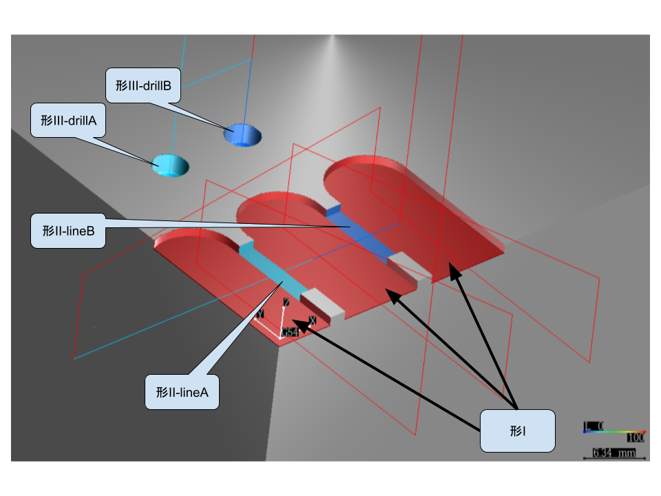
Shape I
Shape I consists of three red slots, which are preparatory shapes, no need to collect smart tool holder data.
- ae10; ap1; S1500; F600
Shape II
Shape II penetrates through the thin walls between the three red slots, need to collect smart tool holder data.
- lineA: T1; ap1; S50; F20 (frt0.1)
- lineB: T1; ap1; S50; F10 (frt0.05)
Shape III
Shape III is drilling, need to collect smart tool holder data.
- drillA: T2; dp4; S50; F20
- drillB: T2; dp4; S50; F10