Primary Relief Angle Clearance
All relief angles discussed in this article refer to the primary relief angle — the relief angle closest to the cutting zone. Also known as the clearance angle.
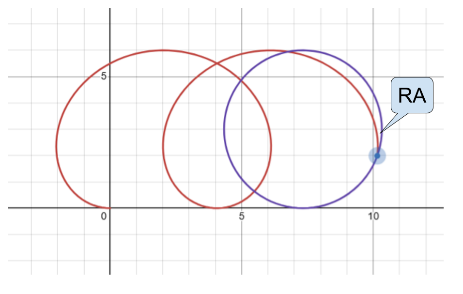
During cutting, the milling cutter edge follows a trochoidal motion, shown as the red trochoid in the figure below. The blue circle is the tool envelope circle.
The region inside the red trochoid (toward the center of the envelope circle) is the already-cut area; the region outside the red trochoid is the uncut area. If the relief face falls in that region, it will collide with the uncut material. Therefore, the angle marked RA (abbreviation for Relief Angle) represents the minimum required relief angle.
If the actual tool relief angle is smaller than the minimum required relief angle, the clearance face will press against the uncut workpiece, increasing forces on both the tool and the workpiece. This leads to greater tool vibration, workpiece surface springback, a sharp rise in surface roughness, and reduced tool life.
Minimum Required Relief Angle Calculation
For fixed-axis machining, the minimum required relief angle can be calculated from the feed rate, spindle speed, and tool radius. For simultaneous multi-axis machining, it must be computed in batch for each contact point along the program path.
The following outlines the calculation for fixed-axis machining.
\(\vec r_p = \left(t\cdot v-R\cdot\sin\left(t\cdot w\right),R-R\cdot\cos\left(t\cdot w\right)\right)\)
\(\vec r_b = \left(a\cdot v-R\cdot\cos\left(s\right),R-R\cdot\sin\left(s\right)\right)\)
Where: \(\vec r_p\) is the position vector of the red trochoid; \(\vec r_b\) is the position vector of the blue circle; \(R\) is the tool radius (mm); \(w\) is the spindle speed (rad/s); \(v\) is the feed rate (mm/s); \(t\) is time; \(s = t\cdot w\); \(a\) is a specified time, used as a constant.
Let the velocity vectors be
The angle between \(\vec v_p\) and \(\vec v_b\) is the minimum required relief angle.