Milling Physics Coordinate Systems
Physical properties such as milling forces, milling torques, and deformations can be represented in different coordinate systems. Sensor raw data also corresponds to different coordinate systems.
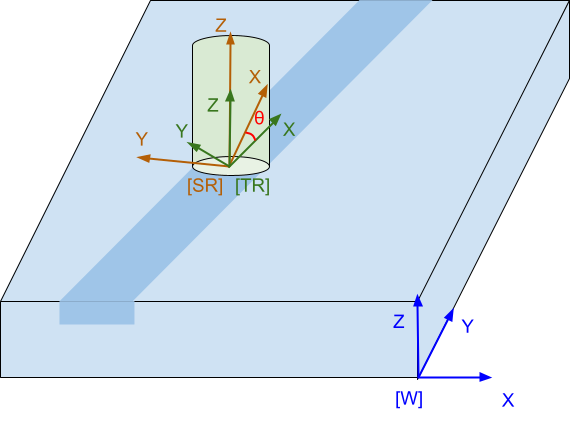
When viewing physical simulation data in HiNC, you will often see coordinate system notations. This chapter explains the three coordinate systems shown in the figure below.
Note
Workpiece Coordinate System
Workpiece Coordinate System, abbreviated as [W].
Usually the program origin coordinate system.
The workpiece coordinate system is consistent with the dynamometer coordinate system.
Tool Running Coordinate System
Tool Running Coordinate System, abbreviated as [TR].
Takes the tool running direction excluding tool normal movement as +X, tool normal vector as +Z, and defines +Y by the right-hand rule. For climb milling, +Y direction is away from the wall.
The tool running coordinate system is suitable for understanding machining conditions.
Spindle Rotation Coordinate System
Spindle Rotation Coordinate System, abbreviated as [SR].
The tool running coordinate system rotated around the Z axis by spindle motion angle \(\theta\) becomes the spindle rotation coordinate system.
The spindle rotation coordinate system is consistent with the smart tool holder coordinate system, as the smart tool holder sensor rotates with the spindle.